Linear Collider Final Focus Magnet Construction
Single Strand Superconductor Windings
Initial direct wind quad coils were constructed using 13 mil diameter single strand wire. This wire provides the smallest coil patterns possible, with quad coils wound easily onto .75 inch (19mm) diameter support tubes. The 13mil diameter superconductor gives the smallest coils possible, the penalty being higher inductance and smaller transfer function, but allowing lower operational currents.
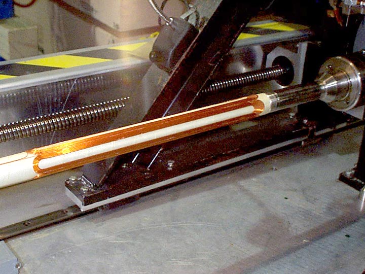
Figure 1 shows the first one foot long model magnet constructed using the 11 axis ultrasonic wiring machine with 13 mil superconducting wire, the same wire previously used for the 472 RHIC Corrector packages. Existing stock materials were used in the construction, and the coil pattern was not optimized for harmonics, but to put as many coil turns onto the tube as possible.
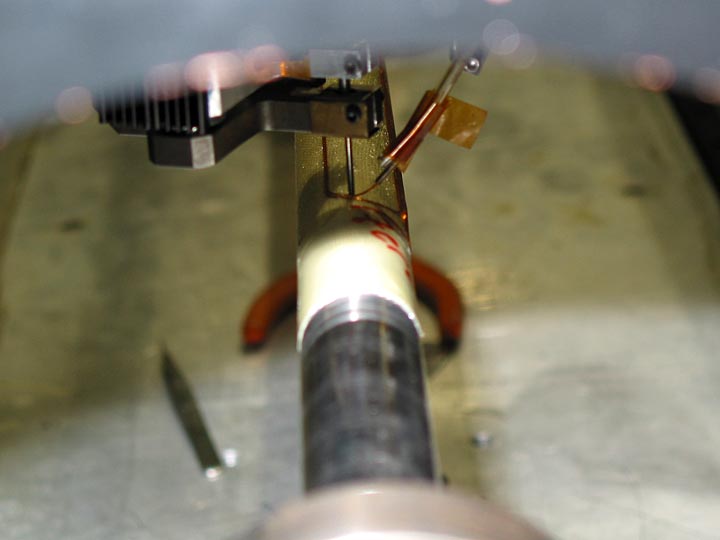
The second test magnet, wound using the same diameter tube, was extended to three feet. Figure 2 shows the wiring head planting the second turn of the first pole, layer 1, at the non lead end of the pattern. Two layer patterns are wound by spiraling in to the pole, climbing up to the second layer, and spiraling out. Once a pole is finished, the machine moves on to the next pole.
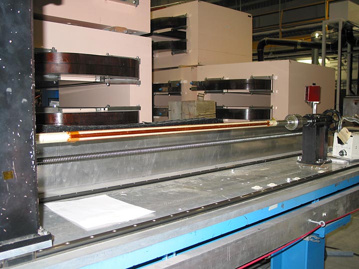
Figure 3 shows the completed 3 foot long test magnet. One of the primary issues surrounding the use of such a small diameter tube, is the flexing of the tube during the wiring process.
To stop flexing of the tube, a mechanical support fixture has been included. It is centered on the length of the tube, and has radial spokes engaged into a Teflon circular, captured bearing assembly. Measurement of the tube for roundness and rotational errors verify the support structure works, and it is easily capable of supporting the ultrasonic wiring process down pressure, typically 120 grams for 13 mil wire bonding.
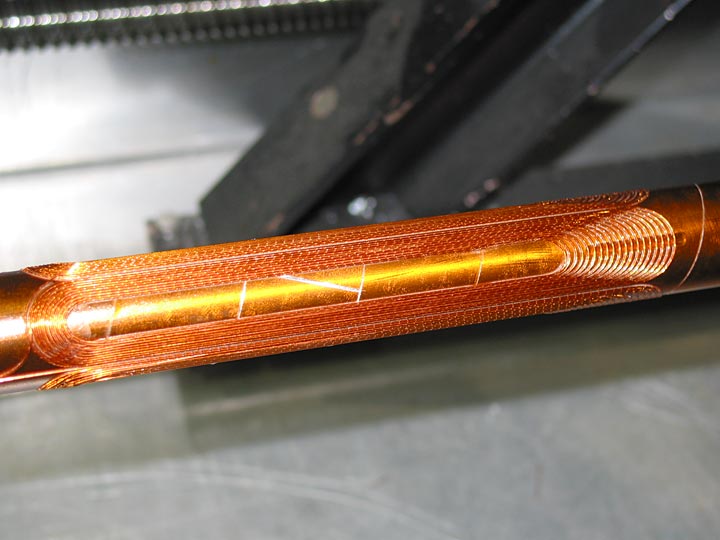
Figure 4. The first wire pattern tests used an 11 turn, standard four pole quad pattern. The lead end of the pattern is the same as typical RHIC corrector patterns, with tight end turn spacing, and spiral in and out transitions on the lead end. The non lead end was fluffed, with an arbitrary spacing placed between turns. This two layer pattern also has the second layer nested between the wires of the first, and at the non lead end, the fluff region is also nested, although the layer two wires drop to the substrate surface, reducing the effective diameter of the end. Fluffing the lead end is not an option for this coil design type.
Next, a serpentine quad pattern was developed. By using a serpentine pattern, the midplane gap between poles is eliminated, as well as allowing a wire to be placed directly on the midplane. This provides a higher transfer function than the discrete pole option.
Figure 5 shows the first layer of a test serpentine quad wound on the 1 inch diameter support tube. Visible is the substrate sections which are added after the first layer is wound, used to raise the turn wires of the second layer, allowing a smooth transit off and on the first layer wire pack.
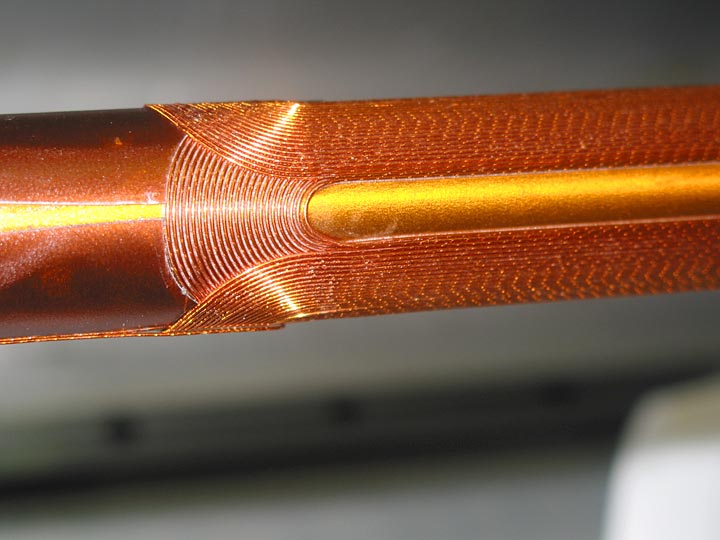
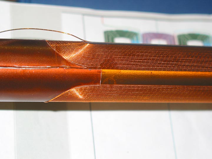
Figure 6 shows the completed serpentine quad. Note that in the straight section, the second layer wires are nested within the spacing of the first, and also note the lack of a midplane in the pattern. Visible in the bottom of the tube is the lead-in and lead-out wire, while in the middle of the visible pole, is the transition point where the wire climbs to the second layer.
The bonding sequence for the newly developed serpentine patterns require placement of one wire per pole for every rotation of the support tube. The old wiring method produced one entire pole at a time, and the support mechanism was designed to allow wiring in that fashion. Since the serpentine pattern requires access to all poles during the winding of one layer, a new center support technology was required.
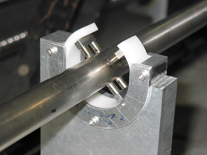
Figure 7 shows the new center support fully built and in place. Note the spokes of the support are now welded stainless, of a thickness smaller than the pole width of the pattern. These welded spokes will remain with the magnet, and will be useable for aligning this completed four layer magnet within the support tube of the outer quad coil support tube.
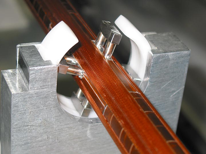
Figure 8 shows the finished two layer NLC quad pattern where the pattern goes past the center support structure. The clearance from the wiring head to the posts is about 25 mils during winding. The white plastic is a delrin bearing surface for the post tips, and is designed to provide centering capture over 270 degrees of arc.
To increase the transfer function, the wire spacing was reduced to 22 mils center to center, and the number of turns was increased to 24. The origional pole width of 32.6 degrees was maintained, this being a current limitation of the winding process with it’s turn radius capability.
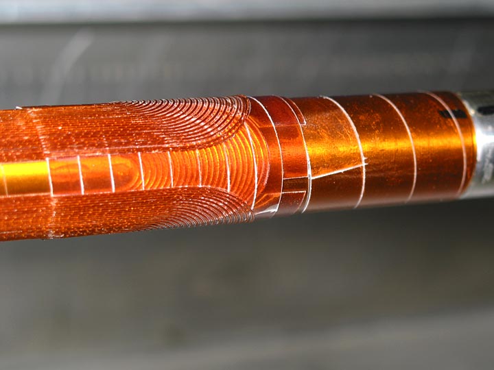
Figure 9 is a picture of the non lead end of the serpentine magnet. Both layers of the pattern can be seen. The wires are placed directly onto the first layer wires in the straight section, and on a second layer of substrate at the ends. This design does not allow arbitrary second layer patterns, and causes faster buildup at the ends.
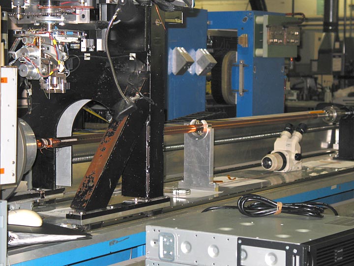
Figure 10 shows the two layer magnet completed but still on the wiring machine.
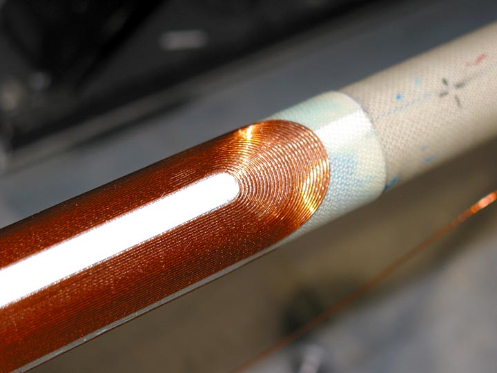
Figure 11 is the next design iteration, this being a 1.65 meter long, three layer pattern. Shown here is the completed second layer prior to the start of the third. Note the full substrate under this layer, as well as the 15 mil thick nomex pole fill material. This allows each layer to be entirely independent magnetically as well as geometrically, and also produces a uniform radial buildup of layers. For this run, the first layer is a planar pattern, the second and third are serpentine patterns. All three layers were bonded using a fiberglass impregnated substrate which was optimized for use with the smaller diameter 13 mil superconductor wire.
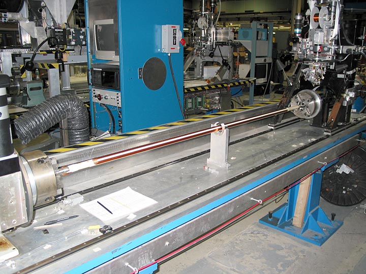
Figure 12 shows the completed 3 layer quad.