BEPC-II Magnet Project
Production Winding
Initial design and production testing finished, the magnet was started.
Test results to date show all coils exceed operational currents, in all powered configurations required.
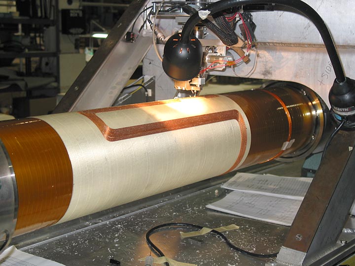
Figure 13 is the start of the first main quad layer. Note the Kapton insulation tube over-wrap. This provides a 5 kilovolt dielectric isolation between all the coils and the ground of the support tube. This isolation is required for protection from voltage breakdown during a quench.
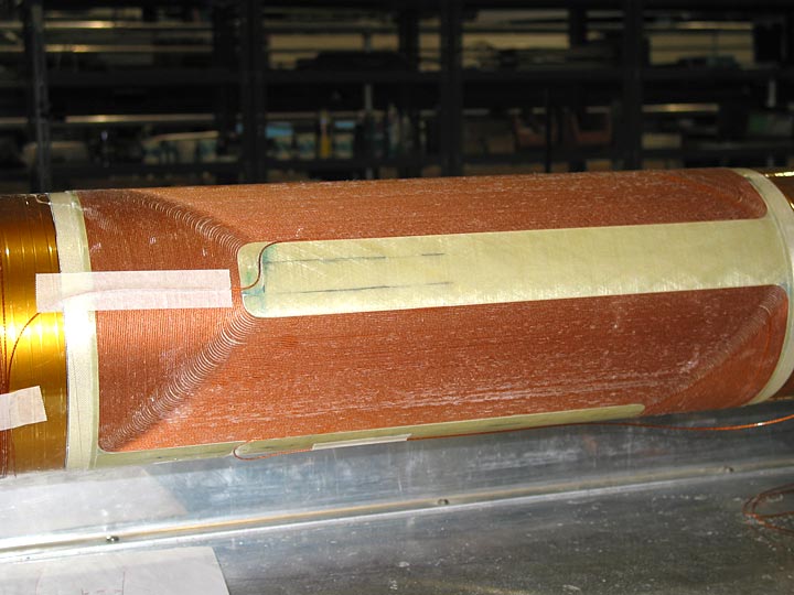
Figure 14 shows the completed layer 1.
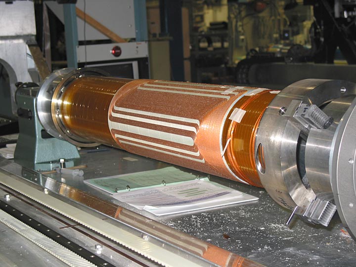
Figure 15 shows the finished second layer.
Note the patterns for each layer. To expedite fabrication, the first layer of each coil pair was designed only for transfer function, no spacers were put into the pattern, and the wire to wire spacing was set to the minimum allowed. All harmonic correction was done on the second layer of the coilsets. By following this procedure, it reduced the amount of effort required to fill the interstitial spaces on the first layer. The second layer g-10 work could be done after the tube was removed from the winding machine, allowing the second magnet to be wound while the first was offline.
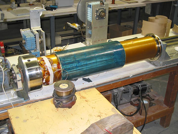
Figure 16 shows the completed 8 layer main quadrupole coilset with the leads being stabilized.
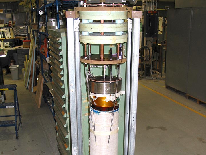
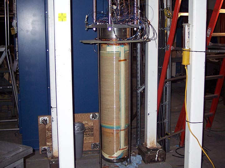
Figure 17 shows the 8 layer quad coldmass being prepared for initial cold tests of the quad. The Direct Wire design includes s-glass precompression wraps, so it is trivial to power the individual quad package prior to completion of the entire magnet structure, the quad is capable of withstanding cryogenic full power operation as a standalone magnet. Testing of the 8 layer quad to beyond full power operation proved the magnet as capable of meeting design goals.
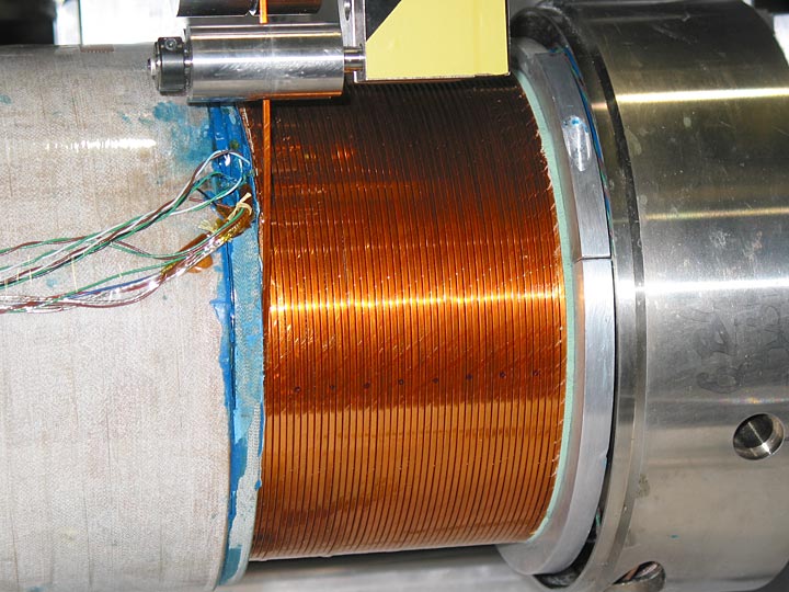
Figure 18 is a closeup of the first of three anti-solenoids being wound. This is a 6 layer construct using standard MRI superconductor, a rectangular cross section wire insulated with kapton.
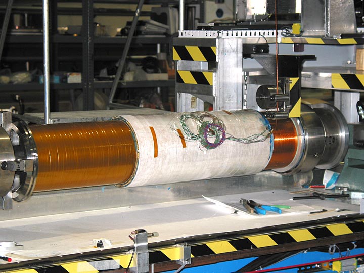
Figure 19 shows the relative location of the first solenoid on the cold mass, it is located on the non lead end. A second 6 layer anti-solenoid is located on the tube at the lead end. After both solenoids are completed, they are over-wrapped to bring the outer surface to that of the main quad coils. This provides the surface for the next set of coils.
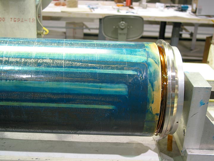
Figure 20 is the completed two layer horizontal dipole coil, shown here after the completion of epoxy filling and curing. It was constructed using the 6 around 1 cable.
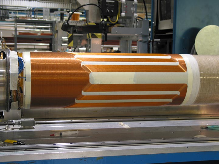
Figure 21 is the completed vertical dipole coilset. It is shown here just after completion of the second layer of the coilset, but prior to the installation of the nomex filler pieces and matched epoxy.
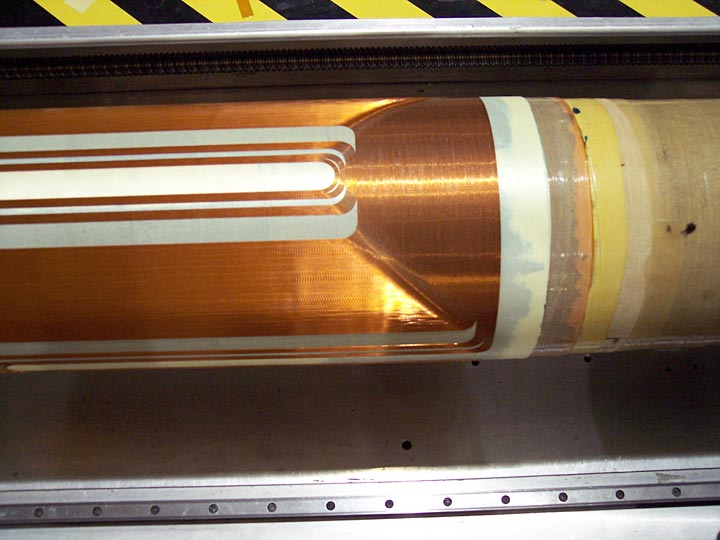
Figure 22 is the completed skew quad coilset, this coil composed of single strand wire. Note the varying harmonic spacers and pattern variations which can be designed into the wiring pattern.
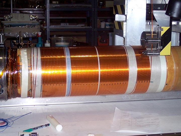
Figure 23 shows the final anti-solenoid being wound. Of interest here is the four section design. By simple programming, it is possible to create independently each block and spacer. After all blocks on one layer are complete, the layer is filled with G-10 spacers and matched epoxy, allowed to room temp cure, and prepped for the next layer.
After all coil winding, wrapping, and curing, the cold mass was connected to a vertical top hat and put through all it’s operational tests. Figure 24 is the cold mass hanging from the top hat and being wired.