HERA Upgrade Project
As part of the HERA luminosity upgrade, 6 superconducting Interaction Region quadrupoles were delivered, accepted, and are in service. These 6 layer magnets were designed to include the main quadrupole focus, a skew quad, a normal and skew dipole, and a final sextupole layer.
Because of the physical space constraints imposed by the existing detector region components, the DESY magnets were of necessity designed to be very compact. In addition, they are also are required to operate within the solenoidal detector fields at the collision points, so all construction materials had to be non magnetic.
Two types of DESY magnets were fabricated. The first, designated as G0, was a two meter long, constant radius magnet. The second, designated GG, is a one meter long, tapered tube, with a continuously increasing field strength from the lead end towards the collision point.
Coil patterns for the magnet were developed by the physicist, translated into a wiring file, and transferred to the 11 axis wiring machine for use in point to point ultrasonic wire bonding.
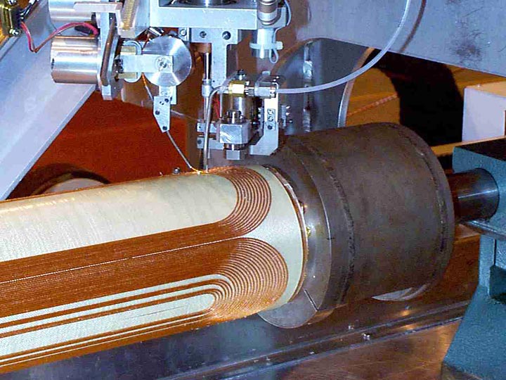
Figure 1 shows one of the machines as it bonds a layer onto the support tube.
This technique allows the use of pattern modulation, allowing the entire coil pattern to be modified to provide zero integral field error.
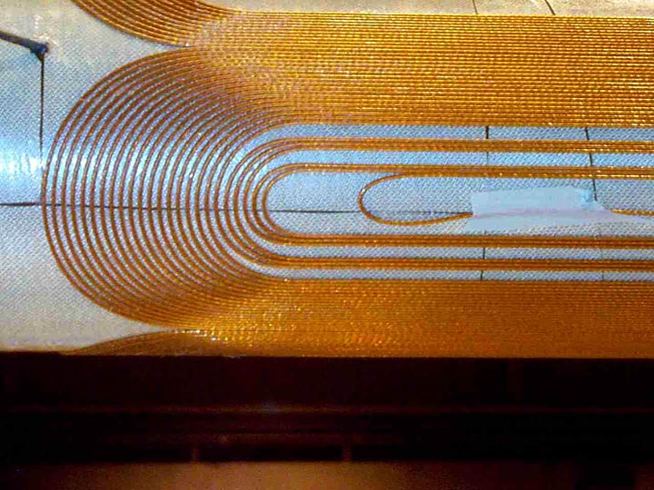
Figure 2 shows one of the three layers of quadrupole completed, and ready for the placement of g-10 shims and overlying compression wraps for mechanical stability. Also evident is the method of modulating the pattern to accommodate peak field issues, as well as harmonic modulation of the final magnetic field. Using arbitrary modulation also allows using subsequent layers to cancel field errors previously measured, reducing the overall harmonic errors of the magnet.
Once manufacturing of the magnet coil assembly is complete, it is placed within the cryostat. The final assembly is comprised of a cold beam tube, external vacuum vessel, end can for all connections, an extension tube, and the electrical feedthroughs. One of each type were put through it’s paces on the horizontal test stand, but all were tested in a vertical dewar for performance.
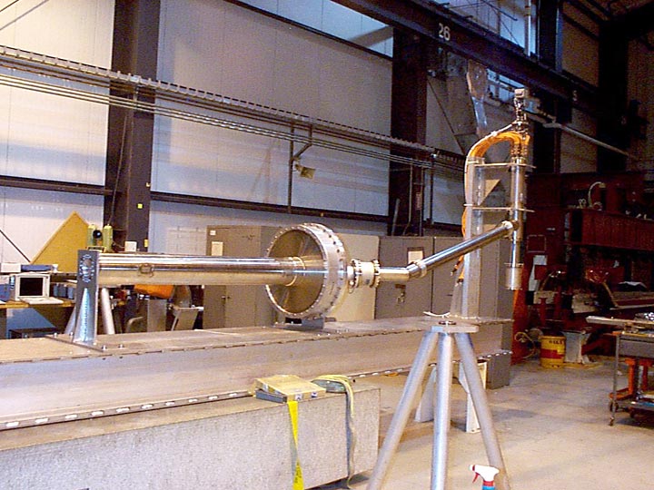
A special transport assembly, Figure 3, was also designed and used to assure the complex structure withstood the rigors of transport to it’s final destination. This picture shows the GG magnet on the transport assembly, ready to be warm tested.
For more information contact John Escallier.