Temporary document
Idea
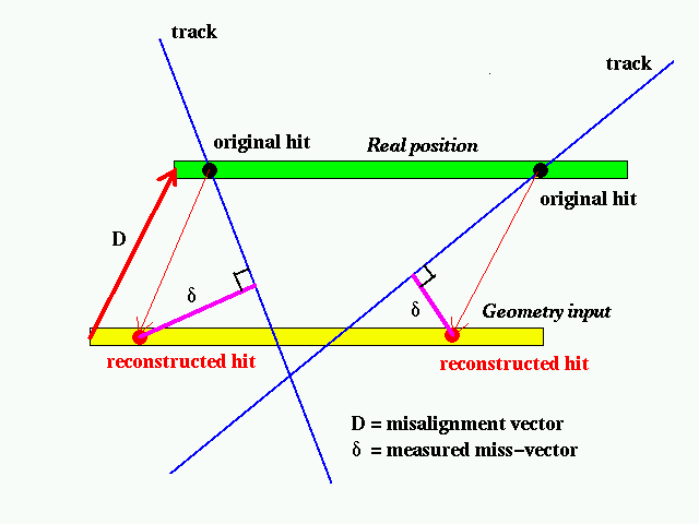
Let's assume that a sensor was put away from the designed position by amount of D.
We will call D Misalignment vector.
We assume also that our geometry file is produced with the SURVEY result, so that the misalignment vectors are generally smaller than 1 mm level.
Our alignment goal is then finding the misalignment vector for each sensor.

As shown in the above picture, if a hit made by a track is reconstructed with the designed geometry input, the position is shifted depending on track's angle. But we can always measure a miss-vector, which is defined as a minimum distant vector from the hit to the track.
Then we can make the following equation,
D * delta = |delta|^2

D_x*delta_x + D_y*delta_y + D_z*delta_z = |delta|^2
where D_x, D_y, and D_z are unknown. In principle, then, we need to have only three tracks to solve the equations and get the misalignment vector D. Since there are numerous systematic effects which smear the hit position and the track paramters, we need to have generally many tracks, not only 3.
The first idea to solve the equation is "fitting". In the fit we try to find the misalignment vector which minimizes
Sum of (D*delta - |delta|^2) over all tracks
Method
In order to check the above idea, I did,
Step 0 : Generation of PHOBOS data with a realistic detector
------

  - Generate an artificially misaligned geometry.
    This is done by editing GCDEFS file by hand.
    A tool for editing GCDEFS file will be available later.

  - PMC control file : RHDATA.align, contains all control card for PMC
    basically, turn off magnetic filed, physical event option with
    random vertex, etc.
    You have to have link RHDATA.align as RHDATA before running phatpmc.

  - run phatpmc

  - root[] .x xGenData.C("my.data.root",1,1000)
    (the 1st argument is the name of output DST file, the 2nd is Run number,
     and the 3rd is the number of events you wish to have)

Step 1 : Reconstruct event & Filling Ntuples
------
  (% at this moment there is only spectrometer tracking in the reconstruction)

  - run phat

  - root[] .x xFillNtuple.C("my.data.root","my.ntuple.root")

  - xFillNtuple.C will read my.data.root, and run the phobos Front-end tracking
    program (Mulguisin4: version for non-vertex seed finder). D0 cut, Z0 cut,
    chi2 probability cut are important paramters for tracking.
    For each track seed, a loop over hit list is done to calculate residuals,
    mis-vector, etc.. (These variables were introduced iduring the 1999 PHOBOS
    Engineering Run.) The out put file "my.ntuple.root" has a single object of
    TPhAlign class. The ntuples are handled via the object for better control
  - In the macro, you can turn on/off ntuples via align->SetSensor(344,1)
    or align->SetSensor(344,0), where 344 is the sensor number, 0/1 is switch.
    You can turn on whole sensors on a layer by
    align->TurnOnSubDetector(det,"SpectN",0); where 0 is the layer number

  % be careful about the file size! if you turn on whole sensors you will get
    few hundreds of ntuples.

  % your comments on ntuple content is welcome.

Step 2 : Histogramming
------

  - If you wish to plot "resx" for the sensor 344 (the first sensor of SpectP),
    do the following step (In principle, the same step as we did with ER)

  - run phat
    root[] TFile *f_align=new TFile("my.ntuple.root")
    root[] TPhAlign *align=(TPhAlign*)f_align->Get("Align");
    root[] TNtuple *ntuple=(TNtuple*)align->GetNtuple(344);
    root[] ntuple->Draw("resx")

  % after getting ntuple everything is the same as before.

Step 3 : Fitting & finding misalignment
------
  (This step is still progressing, but you can test)

  - run phat
    root[] .L xFitAlign.C
    root[] minuit()

  - minuit() will call Minuit package (look CERNLIB) and find the best guess of
    misalignment on sensor-by-sensor bases.

Step 4 : Creation of aligned PHOBOS geometry file
------
  (Not yet done)

  %Step 4 means that our alignement job is done!

// db= debug level
ResultFirst fit result
The sensor PC01 (sensor id=349) was moved to x=+1mm,y=+1mm,z=+1mm from its original position.
Then I generated 1000 low-multiplicity events, and ran the alignment program.
After minuit fitting, I could reproduce the misaligment.
PLEASE READ USAGE FIRST...

Click here to see in PS format