J. Hamblen
University of Rochester
Misalignment in the sensor geometry diminishes the vertex resolution by decreasing the tracklet reconstruction efficiency and increasing the number of "ghost" tracklets. It also causes the deposited energy of a given sensor to deviate from the expected value. The following study explores the severity of these deviations as a result of sensor shifts in the few hundred micron range.
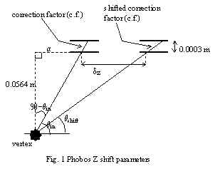
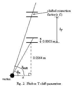
The deposited energy of a sensor is directly proportional to the tracklet length that passes through the sensor. This length of track, known here as the correction factor, will change if the sensor is shifted. Figs. 1 and 2 illustrate the change in correction factor and outline the sensor parameters involved in this study.
![]()
![]()
![]()
![]()
![]() .
.
![]() .
.
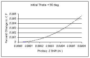
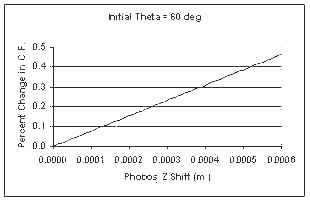
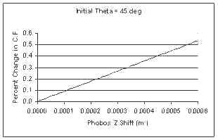
These formulas were used in the following graphs, where the percent change in correction factor is plotted versus the sensor shift (in y and z) out to 600 microns. The initial tracklet angle before shifting is also given.
Phobos Z Shifts

Phobos Y Shifts
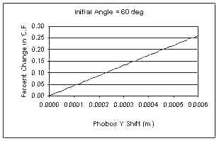
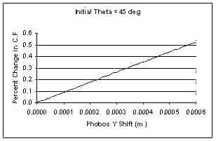
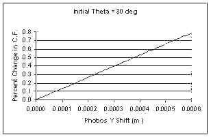
The above plots show that the correction factor changes at most by only a fraction of a percent for a sensor shift of a few hundred microns. Therefore, a negligible change in dE/dx is produced for sensor misalignments in this range.
Page last edited: 08/01/00