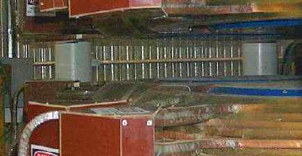
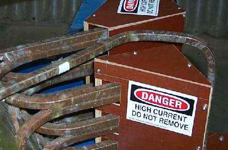
As you can see, the magnet manifolds leave plenty of room for the detector enclosure window and window frame.
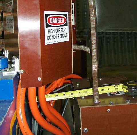
In this edge view, you see that the manifolds stick out quite far (scale in inches!). Also, there are lots of hoses, etc under the manifold covers. Note that it may be possible to redesign the bottom of the cover seen here and redirect the hoses so that a thin bar could pass behind them. However, this will be done ONLY as a last resort if absolutely necessary.
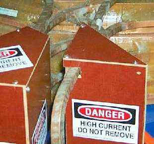
Here you see the gap between the two manifold covers. A vertical support could be added here. The image at right shows the smallest gap which is about 2.5 inches wide. All other gaps are larger. The vertical support could not be in exactly the same place in all four corners but in each case, it would be approximately half way between the second and third holes in from the corner of the pole plate. NOTE that the smaller cover at right does NOT block the pole plate at all.
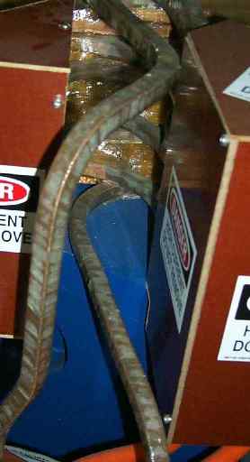
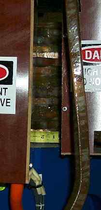
Here you see that in one corner, there are pipes passing through the gap. I believe that it should be possible to insert a vertical support in this area although it might be necessary to bend one of the manifolds slightly.
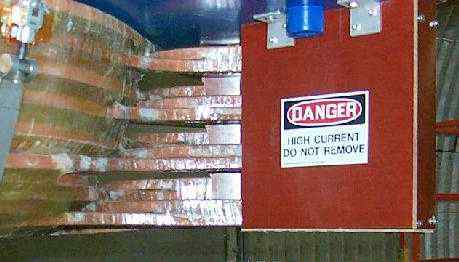
This picture shows that the coil extensions essentially fill all space vertically across the corner where the original enclosure design had a diagonal brace.
Entry posted by George Stephans.
Last edited: Friday, February 04, 2000 01:38:48 PM