
TECHNIQUE AND ANALYSIS OF
THE SURVEY
FOR THE
MULTIPLICITY/VERTEX DETECTOR
Rachid Nouicer and Richard Hollis : May 29, 2001
In this report, we will discuss the techniques that have been used for the hardware survey and also the method used for the analysis of the data survey. At the end of the report, the final results of the survey will be given in the format of the PHOBOS geometry as requested.
1 -
Hardware Procedure :
After mounting of all modules on the frame, the survey was done in three steps :
First step : we put labeling stickers
on the frame, 8 stickers on the front end and 8 stickers on the back end and some of them
are in different places on the frame. Each one of them has labeling ( i.e. see figure
below, if the sticker is on the front end, its labeling will be OFRMx and x = 1 to 8
and if it was on the back end frame the labeling will be OFLMx and x = 1to 8).
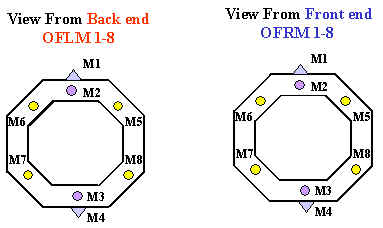
Second Step : "Pre-Survey", the pre-survey was done in the Silicon lab at the Chemistry building. The pre-suvery required us to put the octagon frame with all modules mounted (or Ring counter) in the middle of the room surrounded by 5 to 6 telescopes optical survey equipment (Guns). These Guns shot at all stickers on the frame and give the coordinate (x,y,z,dx,dy,dz) of the center of each sticker relative to some reference. After that, the telescopes shot every sensor located on the frame. For the octagon and outer vertex detectors, we succefully shot 4 points from every sensor. For the Inner vertex, we shot 3 points from every sensor. It was not easy to survey inner vertex, because it was covered by outer vertex. The survey of the 6 ring counters was easy and a good success. Each telescope shot 4 points from each sensor. The figure below shows one ring counter with labeling stickers on the frame front view and back view. The Pre-survey will gives the location of every sensor relative to the frame.

Third Step : after installation of the octagon detector and the 6 ring counters in the tunnel at the final position, we surrounded the detectors by 6 or 8 optical telescopes. The telescopes shot the frame stickers. After that, the analysis of the data survey gave the location of the sensor in phobos coordinates.
The labeling of the stickers, the technique and the different steps of the survey for the octagon and vertex detectors are presented in this file : labeling_survey_technique (click)
2 - Analysis Method :
Comparison between survey 2000 and 2001
(Inclination of the frame) :
The first step in the analysis was the comparison of the frame
position of the octagon between the survey of 2000 (before collision and before switching
the magnet ON) and the survey of 2001 (when everything is done and preparing for the next
run 200 GeV/nucleon). The figure below presents the results of the data suvery i.e. taking
one point from the back end of the frame OFLM1 (see above diagram for
labeling) making straight line to one point from the front end of the frame OFRM1.
From the figure (see below), the black points correspond to old data (survey
2000) and the red points correspond to the new data (survey2001). The same study was done
for the bottom frame (OFLM3 and OFRM3). The results are the following :
From survey 2000 ( see figure below ) : OFLM1(back) - OFRM1(front)
= 68.80 - 67.45 = 1.35 mm
OFLM3(back) - OFRM3(front) = 64.13 - 62.50 = 1.63 mm
this means by just putting the octagon frame with all modules mounted, the front
frame is inclined to the back frame by this mount :
frame inclination front end to the back end (with all modules mounted ) = (1.35 + 1.63) /2 = 1.49 mm in average
From Survey 2000 and 2001 (see figure below) : from the data survey and as presented in the figure below, it seems that the points in the back end of the frame OFLMx (x =1,8) are the same for the survey 2000 and 2001. But there is a little shift for the points located at the front end of the frame comparing data survey of 2000 and 2001. How much ?
Front end frame = OFRM1 (2000) - OFRM1(2001)
= 67.45 - 66.78 = 0.67 mm
OFLM3 (2000) - OFRM3(2001) = 64.13 -
64.87 = 0.74 mm
frame inclination front end to the
back end between 2000 and 2001
(with all modules mounted ) is equal
(0.67 + 0.70) /2 = 0.705 mm in average
This extra inclination of the frame in time can be related to different behaviours, like the frame in time getting his final position on the mechanical support, or can be related to the magnet vibration. Another survey for the octagon frame in 2002 is necessary in order to understand this inclination in time.
Procedure :
General :
The aim of the coordinate transforms performed here was to find the corner pads on each
detector to place in the GEANT geometry and to analyze the data. There were three
main types of detector: the Octagon, Inner Vertex and Outer Vertex. As the points
taken in the original survey were not uniform (i.e. different corners on the detector were
measured), different analysis was required within each detector subset, so 5 programs are
required for the octagon (all C++/ROOT), 2 for the outer vertex(all C++/ROOT) and 1 for
the inner vertex (FORTRAN).
Philosophy:
Three points make a plane, so in theory we can extract every point on the detector. To do
this, the unit vectors were found along two perpendicular sides (i.e. 1,2 and 2,3).
From this the corner pad detectors are extrapolated. For the inner vertex there were
(at most) 2 corners measured, so here these points were used and then the detector lined
up along the coordinate system.
Here you find the programs for
the analysis and how to run them with details
: Analysis_programs
(click)
Final Survey Data in 2001 for the Multiplicity/Vertex Detector (Download by clicking on the file)
- Final_Data_Survey_Results_2k1_Octagon.dat (click)
- Final_Data_Survey_Results_2k1_Outer_Vertex.dat (click)
- Final_Data_Survey_Results_2k1_Inner_Vertex.dat (click)
Note : In order to check the Ring counter, we made a survey for one Ring which has position +1Z and inside magnet. The results of the data survey for this ring (+1Z) in 2001 are identical to the results of the data survey 2000. Conclusion, the new geometry of the 6 Ring counters is based on the data survey results of 2000.
Final Survey Data in 2002 for the Ring Counters 4, 5 and 6 (Download by clicking on the file)
- Macro to plot survey data (click)
- Survey data for the Ring Counter 4 (click)
- Survey data for the Ring Counter 5 (click)
- Survey data for the Ring Counter 6 (click)