
In order to finalize the design of the base for the T0 supports, we need to fix several parameters. The purpose of this document is to show the constraints imposed on the design of the base by what is already installed in the IR behind ring 1 and 2, and to list the questions that will need to be addressed by the experts (Robert Pak and George Stephans).
The previous design drawing shows the T0 support structure, mounted on a U-shaped base. For reference, we have shown a "standard" concrete block inside the U-shaped base (see also the enlarged view of this region shown below). The dimensions of the U-shaped base needs to be fixed, based on the obstructions present in the regions were these counters will be installed. Since the obstructions on the N and P sides are very different, the actual dimensions of the bases will be different on both sides.

The following picture shows a close-up of the region right behind ring 2 on the P side.
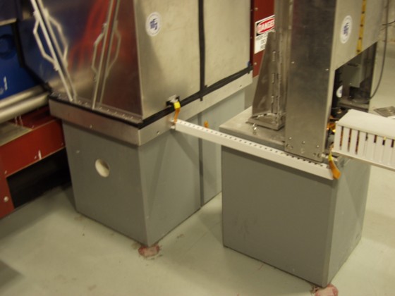
As can be seen in this picture, the only obstruction in this region is the cable tray. The height of the base can be adjusted so that the top of the base is either above or below this cable tray. The width of the base must be wider than the width of the block.
The following picture shows a close-up of the region right behind ring 1on the N side.
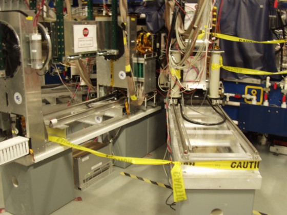
In this region, the base must be high enough to clear the rails. No matter how we design, the base will limit access to the power supply that is mounted below the rails between the concrete blocks. We should consider if it is necessary to move this supply.
From a design point of view, there is great flexibility in the dimensions of the base. The actual height of this base can be compensated easily by adjusting the size of the rod that supports the T0 mounting frames. In order to proceed with the final design, we need input from the experts and answers to the following questions:
Note: the answers to the above questions must be based on the actual dimensions on what is mounted on the floor and how much clearance is required by the experts between the base on the various obstructions.