Beam Diagnostics
Beamline Spectrometry
Both ATF beam lines have dipoles, which serve as spectrometers, the vacuum chambers on of these dipoles also have zero degree ports that may be covered with a Beryllium window for x-ray diagnostics, down stream of the Interaction chamber. Both dipoles are currently serving as spectrometers.
A 90-degree dipole placed at the end of beam line #1 and assembled with a phosphor screen, high resolution camera and Faraday cup serves as an e-beam spectrometer to measure charge and energy distribution in the bunch. The electron beam spectrometer located at the end of beam line #2 consists of a dipole magnet, four quadrupoles, a beam dump with a phosphor screen and high resolution camera, and a Faraday cup. Quadrupoles are used to achieve small horizontal beta-function and high dispersion at the phosphor screen for energy resolution better than 30 keV.
ATF Strip-line Electron Beam Position Monitors
- Four strip-line electrodes in a 1 1/2" stainless tube with 2 3/4" conflat flanges.
- Microwave receiver based on Double Balanced Mixer downconversion.
- Cutaway drawing of the strip-line electrode beam line assembly
- Photograph of the microwave receiver
- Response of the strip-line electrode to an electron bunch, measured with a single-shot oscilloscope (time domain)
- Response of the strip-line electrode to an electron bunch, measured with a fast oscilloscope and converted to the frequency domain
- Output of the strip-line BPM following the receiver and analog amplification calibrated against a CCD camera Pop-up profile monitor
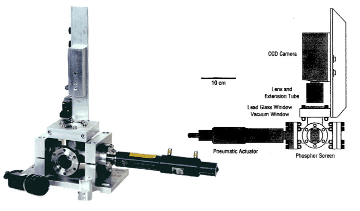
"Pop-Up" Electron Beam Profile Monitors
The ATF has a large number of "pop-up" beam profile monitors that are compact, inexpensive exhibiting fast insertion and extraction. The read-out is thru a CCD camera and a frame-grabber. The large number of beam profile monitors, coupled with multiple TV monitors and frame-grabbers at various locations at the ATF requires the use of a computer driven video multiplexer. The video multiplexer is used to assign a pop-up to a monitor or frame-grabber at the time of insertion.
- Schematic of pop-up monitor arrangement
- Table of monitor details
- Measured video camera resolution
- CCD camera pixel responsivity comparison
- TM-745E User Manual
- GigE CCD cameras
- Users' Manual CCD Image Sensor specs
Pop-up Beam Profile Monitor
Video Frame Grabber' FAQ & Tips
- Part 1. Working with ATF Frame Grabber
- Part 2. Saving and recalling images and their associated color maps
- Part 3. Re-creating images from captured data
- Part 4. Tips and Techniques
RF Systems
In order to synchronize linac and laser components, all RF signals at ATF are derived from one Master clock in Laser room. For instance, some RF are then sent to YAG system to lock a laser oscillator and some are converted to high power RF in Mezzanine. In addition, RF signals are picked up from RF waveguides and cavities for monitoring them. The picked-up RF are once sent to Mezzanine and then forwarded to each monitor such as oscilloscopes in the control room.
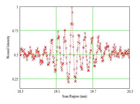
Longitudinal Beam Profile Measurements
In order to measure longitudinal beam profile is used coherent transition radiation from the electron beam. ATF has interferometer, Golay cell and bolometer to measure the longitudinal profile. Measured longitudinal beam profile for PWFA experiments is shown in following figure.