Electron Beam Systems
The ATF offers users access to two 75 MeV, high-brightness electron beam lines. These beam lines can be used in conjunction with the range of laser capabilities at the facility.
Electron Beam Systems Capabilities
Photoinjector
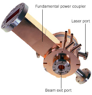
The ATF photoinjector is an S-band (2.586 GHz), 1.6 cell, water cooled, elliptical, copper, cavity maintained at a base pressure of ~ 1x10⁻¹⁰ Torr. Two ports symmetrically placed in the first 0.6 cell are used for laser irradiation and imaging of the cathode. One port in the full cell is used for coupling fundamental power and a second port is placed to preserve the symmetry. RF coupling into the half-cell is through the iris.
The gun is powered by SLAC XK-5 klystron delivering a maximum power of 10 MW, typically run at 2.5 MW in 2.5 µs pulse. The design accelerating field is 100 MV/m and corresponding peak accelerating and surface fields are 130 MV/m and 160 MV/m respectively. A combination of two solenoids, one at the exit of the gun and another at the back of the gun provide emittance compensation to the electron beam while maintaining zero longitudinal magnetic field at the cathode. The center of the removable back flange serves as the cathode. Quantum efficiency of the laser cleaned copper cathode is typically in the range of 0.3-0.4%.
S-band Linac
Some experiments at the ATF require higher energies than what is available from the photoinjector. We use two traveling wave linac structures, known as 'SLAC sections' (from the famous 2-mile SLAC linac). Each section provides an acceleration given by:
Energy gain (in MeV) = 10.8*SQRT(Power in MW)-39.5*Current(in amps)
The current to be used is an equivalent steady state current. The microwave drive power, at a frequency of 2856 MHz, is provided by a single XK5 klystron tube (the old SLAC klystron). This tube can provide up to 25 MW. The ATF modulator can provide the XK5 klystron with high voltage for about 3 microseconds. This 3 microsecond pulse is called the macropulse. The repetition rate for the macropulses is from 1 to 6 per second. Within each of these macrobunches we accelerate from 1 to about 200 electron bunches (depending on the photoinjector's laser setting). These current bunches are called micropulses. The micropulse repetition rate is up to 81 MHz.
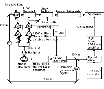
Schematic layout of the ATF linac emphasizing the laser and rf loops, timing and frequencies.
Experimental Hall
High-brightness, up to 75 MeV, sub-picosecond, 3 kA electron bunches are delivered to the experimental hall where user experiments can be executed on two beam lines as shown below. The experimental beam lines are fully equipped with beam manipulation and diagnostic capabilities as well as special insertion devices to support diverse user requirements. The unique capabilities available at the ATF include the possibility to combine the electron beam with synchronized high-power long-wave infrared (LWIR) and near infrared (NIR) lasers. Typical operating parameters for the electron beam are enumerated in
Electron beam diagnostics include spectrometer magnets at the end of each beamline, strip-line beam position monitors, beam profile monitor screens along with video frame grabbers in the control system, and various longitudinal beam profile diagnostics. The most sensitive longitudinal measurements are provided by the x-band transverse deflecting cavity located after the experimental stations on ATF beamline #2.
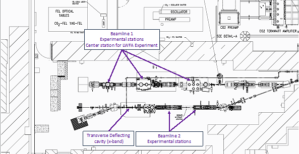
Layout of the ATF electron beamlines and experimental stations.
Beamline Parameters
Electron beam parameters on the ATF beamline
| Parameter | Units | Typical Values | Comments |
|---|---|---|---|
| Beam Energy | MeV | 50-65 | Full range is ~15-75 MeV with highest beam quality at nominal values |
| Bunch Charge | nC | 0.1-2.0 | Bunch length & emittance vary with charge |
| Compression | fs | Down to 100 fs (up to 1 kA peak current) | A magnetic bunch compressor available to compress bunch down
to ~100 fs. Beam quality is variable depending on charge and
amount of compression required. NOTE: Further compression options are being developed to provide lengths down to the ~10 fs level. |
| Transverse size at IP (σ) | microns | 30-100 (dependent on IP position) | It is possible to achieve transverse seizes below 10 um with special permanent magnet optics. |
| Normalized Emittance | microns | 1 (at 0.3 nC) | Variable with bunch charge |
| Rep. Rate (Hz) | Hz | 1.5 | 3 Hz also available if needed |
| Trains mode | --- | Single bunch | Multi-bunch mode available. Trains of 24 or 48 ns spaced bunches. |
Beamline characterizations below have been presented by D.T. Palmer, X.-J. Wang, R.H. Miller, I. Ben-Zvi, C. Pellegrini, J. Sheehan, J. Skaritka, H. Winick, M. Woodle and V. Yakimenko, Commissioning Results of the Next Generation Photoinjector, Proc. 7th Advanced Accelerator Concepts Workshop, Lake Tahoe, Oct. 13-18, 1996.
- Electron bunch length (full width, ps) vs. charge for three rf phases.
- Measured normalized rms emittance as a function of the laser to rf phase at a constant laser energy.
- Measured normalized rms emittance as a function of the charge at a constant laser to rf phase.
- Measured charge, pulse length and the resultant current as a function of the phase at a constant laser energy.
- Electron charge vs. laser intensity, various cathodes and cleaning conditions.The charge is in nano Coulombs, the UV (quadrupled YAG) laser energy in microJoules.
Magnetic Element Parameters
| Aperture | Maximum Current | Voltage Drop | Slope | Effective Length | |
|---|---|---|---|---|---|
| BEPC quad 1X | 40 mm | 25 A | 0.06 V/A | 22.1 G/cm/A | 10.4 cm |
| BEPC quad 2X | 40 mm | 25 A | 0.1 V/A | 22.1 G/cm/A | 20.4 cm |
| SLAC 1X | 28 mm | 10 A | 0.63 V/A | 178.0 G/cm/A | 10.16 cm |
| SLAC 1X | 28 mm | 10 A | 1.1 V/A | 181.5 G/cm/A | 20.32 cm |
| 6Q40 "Small" | 40 mm | 10 A | 0.63 V/A | 50 G/cm/A | 7.6 cm |
| Aperture | Maximum Current | Voltage Drop | Slope (see calibration curves) | Effective Length | |
|---|---|---|---|---|---|
| Dipole 20 deg. | 60 A | 0.19 V/A | 52.4 G/A | 40.0 cm < | |
| Spectrometer dipole 0-8 deg. | 30 mm | 24.0 cm | |||
| Solenoid | 80 mm | 200 A | 0.1 V/A | 14.0 G/A | 19.5 cm |
| Steering coils: | |||||
| Inside solenoid IN/OUT | 40 mm | 1 A | 49.97/40.83 G/A | 10.2/10.5 cm | |
| "Slim" trim | 70 mm | 4A | 25 G/A | 0.8 cm | |
| "Old" trim | 5A | 7 G/A | 17 cm | ||
Beam Diagnostics
Beamline Spectrometry
Both ATF beam lines have dipoles, which serve as spectrometers, the vacuum chambers on of these dipoles also have zero-degree ports that may be covered with a Beryllium window for x-ray diagnostics, downstream of the Interaction chamber. Both dipoles are currently serving as spectrometers.
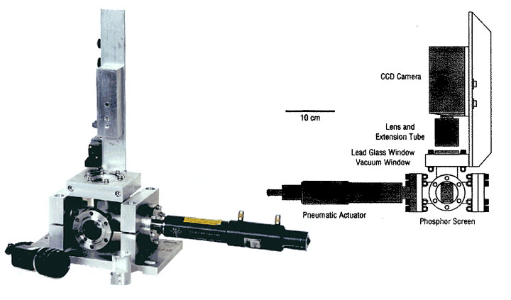
A 90-degree dipole placed at the end of beam line #1 and assembled with a phosphor screen, high resolution camera and Faraday cup serves as an e-beam spectrometer to measure charge and energy distribution in the bunch. The electron beam spectrometer located at the end of beam line #2 consists of a dipole magnet, four quadrupoles, a beam dump with a phosphor screen and high-resolution camera, and a Faraday cup. Quadrupoles are used to achieve small horizontal beta-function and high dispersion at the phosphor screen for energy resolution better than 30 keV.
- Demonstration of different mask techniques and spectrometer images from different experiments conducted at the ATF.
ATF Strip-line Electron Beam Position Monitors
- Four strip-line electrodes in a 1 1/2" stainless tube with 2 3/4" conflat flanges.
- Microwave receiver based on Double Balanced Mixer downconversion.
- Cutaway drawing of the strip-line electrode beam line assembly
- Photograph of the microwave receiver
- Response of the strip-line electrode to an electron bunch, measured with a single-shot oscilloscope (time domain)
- Response of the strip-line electrode to an electron bunch, measured with a fast oscilloscope and converted to the frequency domain
- Output of the strip-line BPM following the receiver and analog amplification calibrated against a CCD camera Pop-up profile monitor
"Pop-Up" Electron Beam Profile Monitors
The ATF has a large number of "pop-up" beam profile monitors that are compact, inexpensive exhibiting fast insertion and extraction. The read-out is thru a CCD camera and a frame-grabber. The large number of beam profile monitors coupled with multiple TV monitors and frame-grabbers at various locations at the ATF requires the use of a computer driven video multiplexer. The video multiplexer is used to assign a pop-up to a monitor or frame-grabber at the time of insertion.
- Schematic of pop-up monitor arrangement | Table of monitor details
- Measured video camera resolution
- CCD camera pixel responsivity comparison
- TM-745E User Manual
- GigE CCD cameras: Users' Manual, CCD Image Sensor specs
Pop-up Beam Profile Monitor
Video Frame Grabber' FAQ & Tips
- Part 1. Working with ATF Frame Grabber
- Part 2. Saving and recalling images and their associated color maps
- Part 3. Re-creating images from captured data
- Part 4. Tips and Techniques
RF Systems
In order to synchronize linac and laser components, all RF signals at ATF are derived from one Master clock in Laser room. For instance, some RF are then sent to YAG system to lock a laser oscillator and some are converted to high power RF in Mezzanine. In addition, RF signals are picked up from RF waveguides and cavities for monitoring them. The picked-up RF are once sent to Mezzanine and then forwarded to each monitor such as oscilloscopes in the control room.
- RF schematics
- Low-level RF measurements
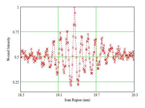
Longitudinal Beam Profile Measurements
In order to measure longitudinal beam profile is used coherent transition radiation from the electron beam. ATF has interferometer, Golay cell and bolometer to measure the longitudinal profile. Measured longitudinal beam profile for PWFA experiments is shown in following figure.