BEPC-II Magnet Project
Initial R&D Winding and Tests
To achieve the current densities required within the quad coils, it was decided to fabricate the magnet using coil pairs, with the S-glass compression applied after each double layer wind. Initial wiring tests were done using a nested pattern.
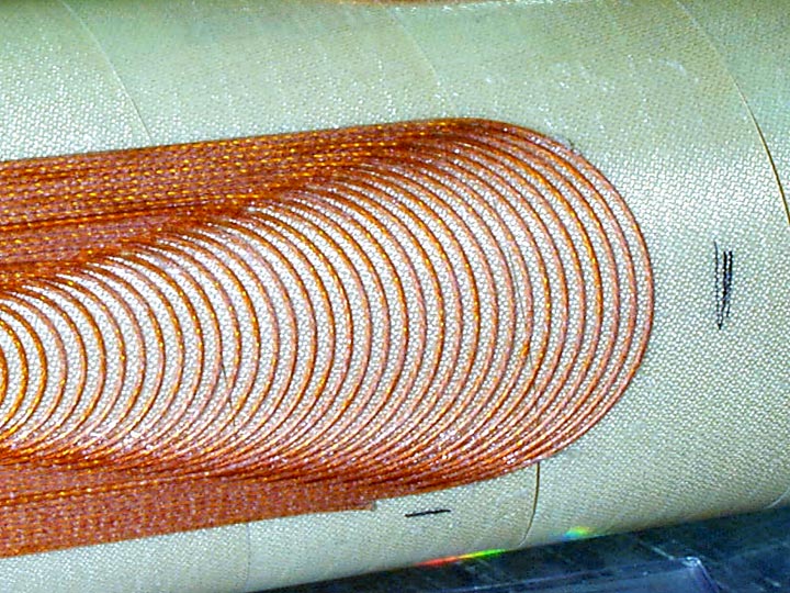
Figure 1 shows this pattern placed the second layer of conductor into the channel formed by the first layer wires, the end of a pole test.
Note the ease with which the second layer wires dropped from the channel on the wires down to the substrate. While producing the highest packing factor in the straight section, it produces a variable height end. This end geometry does not allow a simple layer cover, but requires a very complex top piece. In addition, it does not allow for the simple addition of spacers or modulation of the wire spacing to modify the field quality.
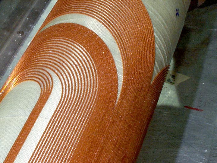
Both of these techniques, a design feature of Direct Wind, is evident in Figure 2. Note the independent capability of straight or end spacers, and the subsection of wires with enhanced spacing. Previous single layer work on the DESY program used seven current blocks for harmonic modification.
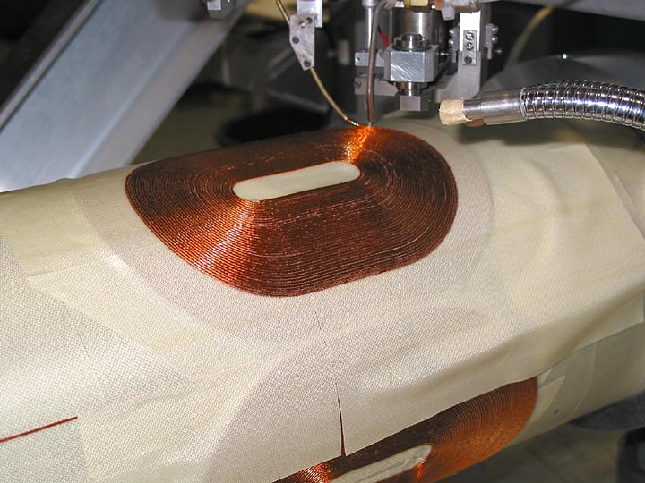
Figure 3 shows the first pass at winding a two layer, separated quadrupole pattern. Shown in the picture is the spiralling out portion on the second layer of the fourth and final pole. Note the layer of substrate that has been placed over the first layer.
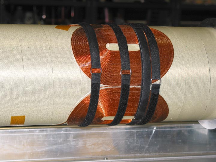
Figure 4 shows the completed quad test coil, with support bands holding the coil radially to prevent long term creep of the coils. This prototype wind pattern clearly demonstrates our capability for 2 layer, substrate-separated coils. This test also provides a focus on aspects of the machine control software needing refinements to further extend our capabilities and design flexibilities.
Further tests of the wiring process will focus on do-decapole patterns with ten turns each layer, to better optimize the process parameters required for coil integrity throughout the inner turns. Once refined enough to meet production requirements, a magnetically correct winding pattern will be planted on the test support tube, and will then be subjected to the next manufacturing step, a vacuum impregnation using epoxy, to further reinforce the coil structure.
For the final solenoid coils, the use of standard rectangular cross section superconductors will provide more stability for the magnet.
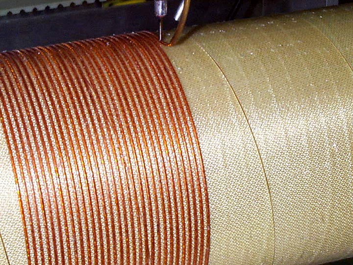
Figure 5 shows a computer wound solenoid using 6 around 1 cable.
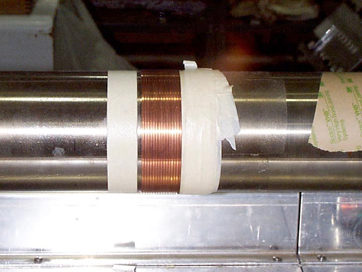
Figure 6 shows a test wind using uninsulated rectangular wire. For the final solenoids, the flat wire will be insulated with Kapton, and the solenoids will be wound on the computer controlled winder platform.
To further optimize both the transfer function as well as winding process, serpentine pattern quadrupoles have been developed. Code has been developed for the inclusion of spacer blocks in the ends, independent by layer as well as by end, for modifying the end harmonic content and to lower the peak field at the pole tips. The ability to modify the wire to wire spacing, as well as additional wire spacing on the end has been retained.
The initial wiring patterns were the traditional, one pole at a time technique, and they require halting the wiring process after each bottom layer coil has been placed, requiring four separate pauses in the wiring, to place g-10 spacer blocks and substrate for layer two winding. This process also requires the application of four, geometry controlled substrate patterns, with accurate placement over the existing wire, all without damaging the first layer wire insulation.
By using a serpentine process, all four poles are planted in one continuous layer. After the full layer has been placed, the process is halted, all g-10 pieces are glued into place, and a spirally wrapped substrate can be wrapped around the first layer winding pattern. This technique reduces both the handling of the coil, as well as easing the manufacturing time required.
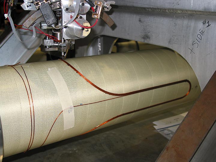
Figure 7 shows the first layer pattern being bonded to the support tube.
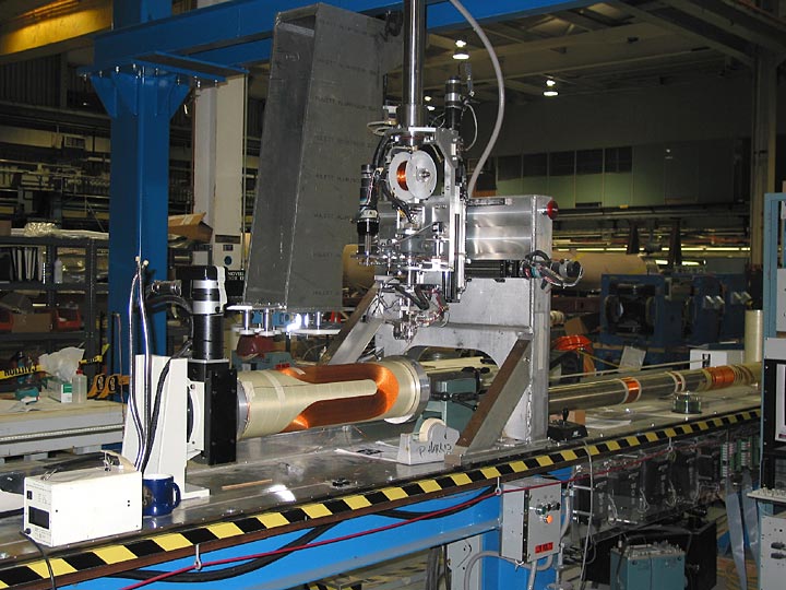
Figure 8 show the completed first serpentine layer prior to application of g-10 and substrate.
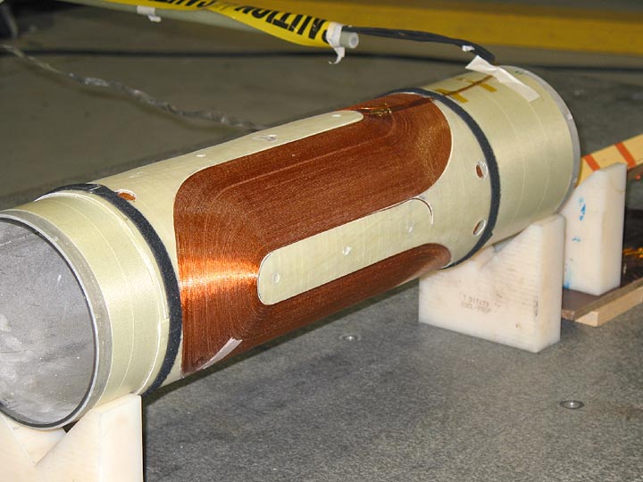
Figure 9 shows the full two layer quad, with all g-10 pieces in place, being tested for magnetic field quality.
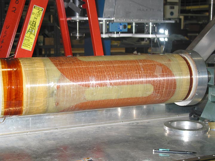
Figure 10 shows the two layer quad after vacuum impregnation, and cold testing at 4.5 K. Designed as a proof of principal coil, this coil was not optimized for harmonics or for suppression of peak fields. As a result, this coil reached 88% of short sample after three quenches, with the next five quenches ranging from 905 amps to 911 amps.
Several of the harmonics measured on the magnet were traced back to a small shift of the tube on the drive support mechanism, approximately 500 microinches per rotation. To verify the engineering correction to the drive mechanism, a magnetically correct pattern was developed, and the tube was stripped down to it’s origional surface for winding.
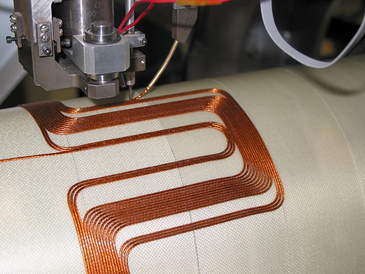
Figure 11 shows a magnetically correct short length engineering test pattern being wound. This test pattern is used to develop the machine control software changes required to accommodate the pattern turn geometry. Once a level of confidence was established, the winding of a full length pattern proceeded.
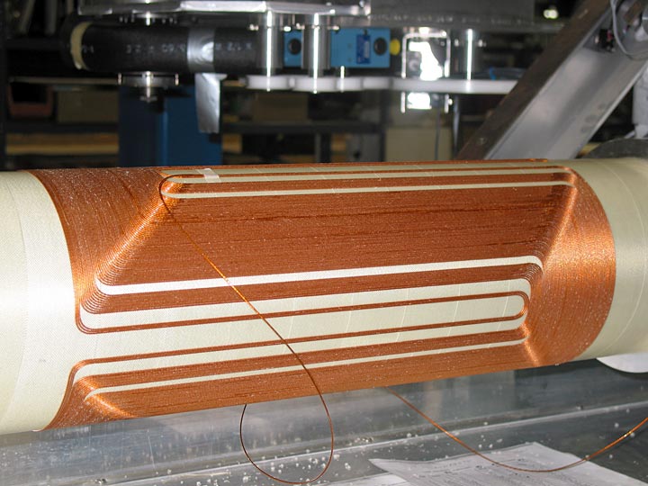
Figure 12 shows the first layer of a full length, magnetically accurate wire pattern. G-10 filler pieces were added, layer two wound, and the magnet met all field requirements.