Bio-Med Variable Field MRI Project
One of the Research and Development projects currently underway is the Bio-Med magnet.
Destined for use within the solenoidal field of an MRI, it is designed for use where the subject, in this case a rat, must be tracked in order to obtain an image. Typical MRIs require the subject to remain stationary, and a rat will not normally oblige when it is awake. By moving the composite field (MRI Solenoid plus Bio-Med dipole) to track the rat, it is possible to allow the rat some freedom of motion, while still imaging the brain functions.
For the rapid movement typical of a rat, the Bio-Med coil magnet must be capable of very rapid changes in field. Superconducting magnets are typically not designed to allow rapid field variations. To do so typically causes the superconductor to quench, a condition which heats the superconductors, ending the superconducting state and forcing the magnet to be turned off.
One of the issues with such rapid field changes is the generation of heat within metals subjected to such field changes. The rapidly changing field is capable of generating kilowatts of heat within a stainless support tube normally used to support the coil. For this reason, the Bio-Med coils are manufactured on a G-10 composite tube. All associated construction materials also need to be non-conducting for the same reason.
Presently, a dipole/skew dipole coil pair has been fabricated and tested for function at high currents and moderate field change rates. The next round of tests will be at 50 Hertz. So far, the coils have followed predicted operation.
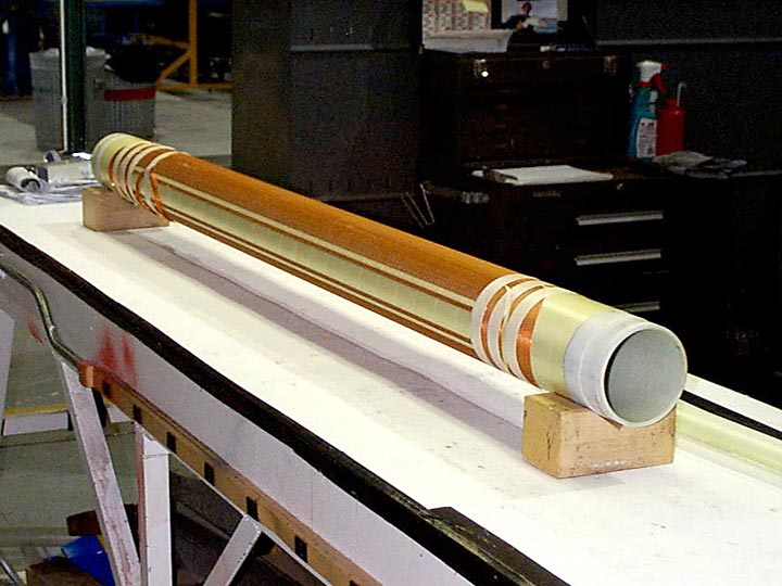
Figure 1 shows the first completed test coil set. The G-10 tube is clearly visible.
To wind the coils, an 11 axis, computer controlled winding machine is used. The machine affords the physicist the flexibility of designing any coil pattern needed, and the manufacturing techniques provide the rigidity necessary to combat the electromagnetic forces that result when the magnet is powered.
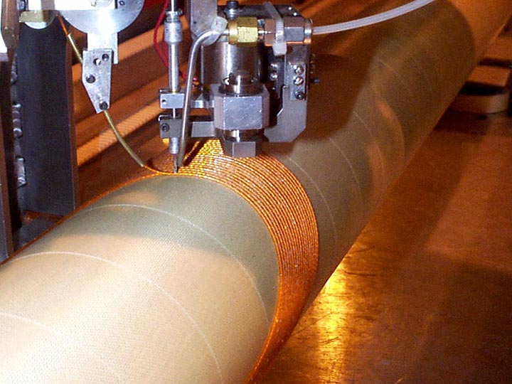
Figure 2 shows the Bio-Med coil being wound on the computer controlled winder. Also visible is the end lead, which exits the coil at the pole.
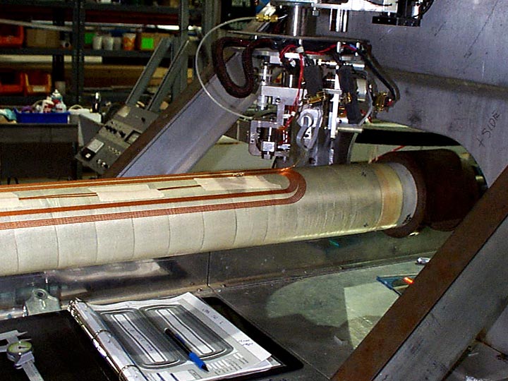
Figure 3 shows the Bio-Med coil being wound on the computer controlled winder. Also visible is the end lead, which exits the coil at the pole.
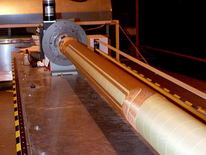
Figure 4 shows the completed first dipole layer, still mounted to the wiring machine.
For more information contact John Escallier.