- Home
-
Compliance
- Environmental Monitoring Plan
- Site Environmental Reports
Pollution Prevention
- Overview
-
Services
Field Sampling
- Overview
- Environmental Monitoring SOPs
- Staff
Env. Compliance Reps
- Process Assessments Forms
-
Resource Management
-
Groundwater Protection
-
Groundwater Protection
Program Overview
Documents and Reports
Groundwater Projects
Surface Projects
Land Use & Institutional Controls Mapping
Groundwater Status Reports
Contact
Reactor Decommissioning Projects
About
BGRR Science & Accomplishments
Celebrating DOE's Cleanup Accomplishments (PDF)
ContactBrookhaven Graphite Research Reactor (BGRR)
Brookhaven Graphite Research Reactor(BGRR) Overview
BGRR Complex Description
Decommissioning Decision
BGRR Complex Cleanup Actions
BGRR Documents
High Flux Beam Reactor (HFBR)
High Flux Beam Reactor (HFBR) Overview
HFBR Complex Description
Decommissioning Decision
HFBR Complex Cleanup Actions
HFBR Documents
-
- Contact
High Flux Beam Reactor Complex Description
Current HFBR Complex
The HFBR complex consists of multiple structures and systems that were necessary to operate and maintain the reactor. The most recognizable features of the complex are the domed reactor confinement building and the distinctive red-and-white stack.
Portions of the complex building structures, systems, and components, some of which are underground, were contaminated with radionuclides and chemicals as a result of previous HFBR and Brookhaven Graphite Research Reactor (BGRR) operations. A number of decommissioning and preparation for long-term safe storage actions have been taken including the removal of contaminated structures, hazardous materials, and contaminated equipment and components. The structures and systems, both current and former, are described below.
The High Flux Beam Reactor complex includes the former Building 704 Fan House; the former Building 802 Fan House; the former Building 715 Stack Monitoring Facility; the former Cooling Towers (ST707); the former Electrical/Pump House (707A); the former Water Treatment House (707B); the Building 705 Stack and Silencer Structure; the Building 750 Confinement Building; the former Building 753 Guard Shack; the Building 751 Cold Neutron Facility Support Equipment; and the former Secondary Water Holdup Tank (310).
Complex Structures
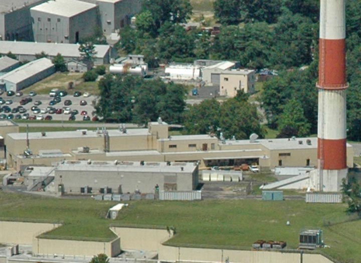
The following provides an overview of the primary HFBR buildings and structures. Figure 1 provides an orientation of the HFBR complex, indicating both existing and former buildings that were once part of HFBR operations.
Building 750, HFBR Confinement Building - Existing
Building 750, which housed the HFBR, is a hemispherical dome and the superstructure of the confinement building. The structure is constructed of welded steel plates supported by an I-beam framework that rests on a cylindrical base. The inside diameter of the hemisphere at its base is 176 feet (ft.) 8 inches (in.). The base is 22 ft. 4 in. high and rests on a bedplate that is bolted to the reinforced concrete foundation ring. The foundation of the confinement building is a 5 ft. thick reinforced concrete mat bearing on the soil beneath the building.
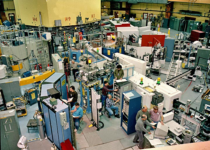
The interior of the confinement building contained the reactor and biological shield and was divided into equipment, experimental, balcony, and operations levels. The operations level contained the control room, instrument and maintenance shops, labs and offices. The equipment level contained the spent fuel pool water purification system, pumps and heat exchangers, cooling systems, and the spent fuel pool. The experimental level was for scientific users. The reactor biological shield, which surrounded the reactor, occupied the central portion of this level. A large open space surrounding the biological shield housed experimental equipment and there were labs and offices along the perimeter wall. Offices, locker rooms, toilets, and HVAC equipment were located on the balcony. The confinement building has four access points: a personnel airlock; a forklift airlock; and two tractor trailer airlocks, one located on the experimental level and one on the equipment level. Most of the HFBR’s systems have been put into a lay-up condition. Only the modified building ventilation, water infiltration, electrical, and security systems remain in service.
The reactor core consisted of 28 individual fuel assemblies arranged in a close-packed array. The fuel material was enriched uranium alloyed in aluminum and clad with aluminum in curved plates, and has been removed and disposed of off-site. Heavy water (D2O) served as the moderator/reflector and primary coolant. The reactor vessel was fabricated from aluminum alloy and contained the active core, reflector, and control rods. The vessel consists of an 82 in. spherical section welded to a 46 in. cylinder. The overall height of the vessel assembly was 24.75 ft. There were nine horizontal beam entry tubes that are integral parts of the vessel’s spherical section. The core region provided space and access for 16 experimental facilities.
Biological Shield - Existing
The biological shield surrounded both the reactor vessel and the 9 inch thick thermal shield. The biological shield remains in place and is 8 feet thick and consists of an inner and outer steel shell filled with high-density concrete. The biological shield also serves as an essential component of the structural integrity of the confinement building. The thermal shield was a carbon steel shell lined with lead.
There were 16 control rod blades (CRBs) within the reactor vessel, which have been removed. They were separated into main and auxiliary groups, each containing eight CRBs. The CRBs operated in the reflector region just outside the core. The CRBs are angle-shaped in cross-section and were made of stainless steel, encapsulating europium oxide and dysprosium oxide.
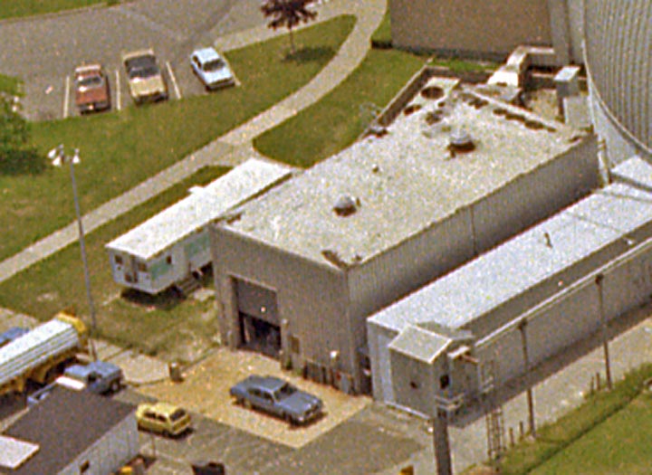
Building 704, Fan House - Demolished
The former fan house was initially constructed to provide primary and secondary cooling air for the BGRR. It enclosed the BGRR discharge plenum and also housed the electrical switchgear and the normal and emergency power batteries for the HFBR. This switchgear also provided normal power to Buildings 703 and 701 and provided the pathway for the HFBR Building 750 exhaust through underground ductwork and filter banks. The Building 704 Fan House has been demolished.
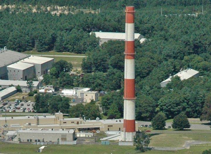
Building 705, Stack - Existing
The 100-meter tall stack was initially constructed for the BGRR primary and secondary cooling air exhaust. Subsequently, additional building exhaust systems were connected to the stack. All exhaust streams were disconnected from the stack, and the stack demolition is scheduled to be completed by 2020.
Building 707A, Electrical/Pump House - Demolished
The Electrical/Pump House was one-story building with structural steel support covered by brick walls and a flat built-up tar roofing system over concrete. The foundation consisted of poured concrete, with a 49,700-gallon capacity sump connected to the cooling tower basin. The pump house contained three of the five secondary cooling water pumps, water tank FA309, and the associated electrical switchgear in an adjacent room. The Electrical/Pump House has been demolished.
Building 707B, Water Treatment House - Demolished
The Water Treatment House was a one-story building with structural steel supports covered by brick walls and a flat built-up tar roofing system over concrete. The foundation consisted of poured concrete. The Water Treatment House was used to store chemicals and contained associated injection, monitoring, and control systems. Cooling water lines, connecting the water treatment house with the secondary water system piping and basin, enabled the chemicals to be injected into the system. The Water Treatment House has been demolished.
Building 715, Stack Monitoring Facility - Demolished
The Stack Monitoring Facility housed the instrumentation used to monitor the stack effluents.
Underground Stack Ventilation Ducts and Lines - Demolished
The underground stack ventilation ducts were the interconnecting ducts from Building 750 and Buildings 801 and 802. Short sections of ducts from Buildings 901 and 701 were also included. The underground stack ventilation ducts and lines were disconnected and removed in 2010.
Building 751, Cold Neutron Facility Support Equipment - Existing
The Cold Neutron Facility (CNF) became operable in 1980, and was developed to provide researchers with a source of very low energy neutrons. The slowing of the neutrons was accomplished by passing the neutron beam through liquid hydrogen in a moderator chamber located at the tip of the beam tube. CNF support equipment, such as the helium refrigerator, was housed in a separate building (Building 751) on the southeast side of Building 750.
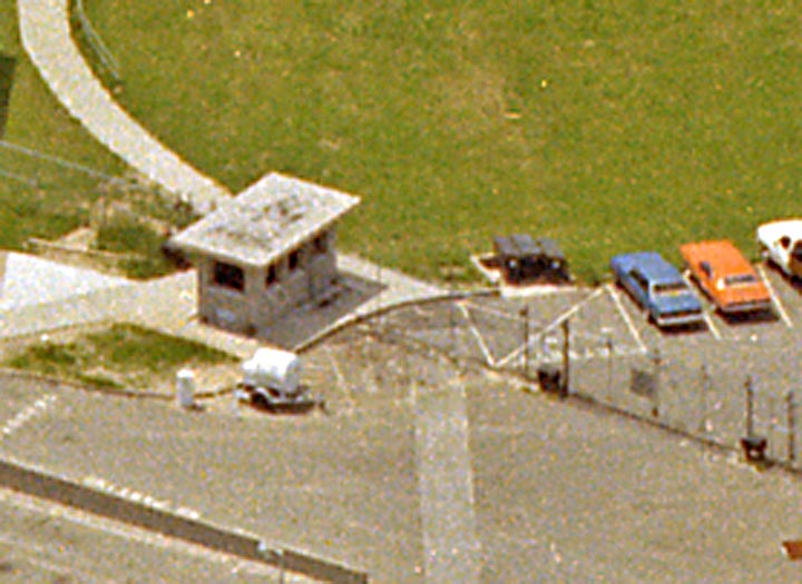
Building 753, Guard Shack - Demolished
The Guard Shack was used by Security personnel on watch.
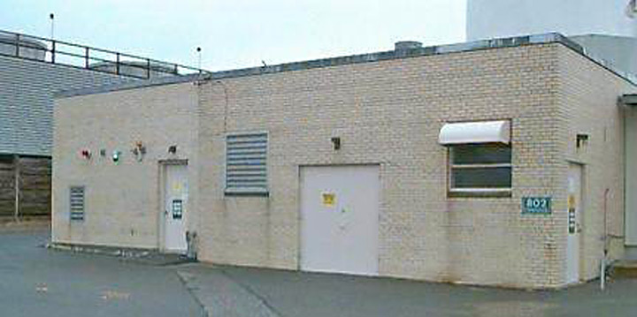
Building 802 - Fan House - Demolished
This structure housed the fans and equipment that provided the building exhaust flow for Buildings 801, 815, and 830. It also housed the equipment for evaporation of low-level tritiated water.
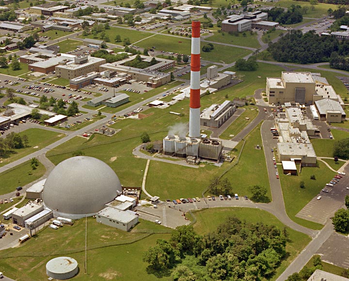
The High Flux Beam Reactor (HFBR) is located in this central portion of the BNL property. The HFBR complex covers approximately 13 acres.
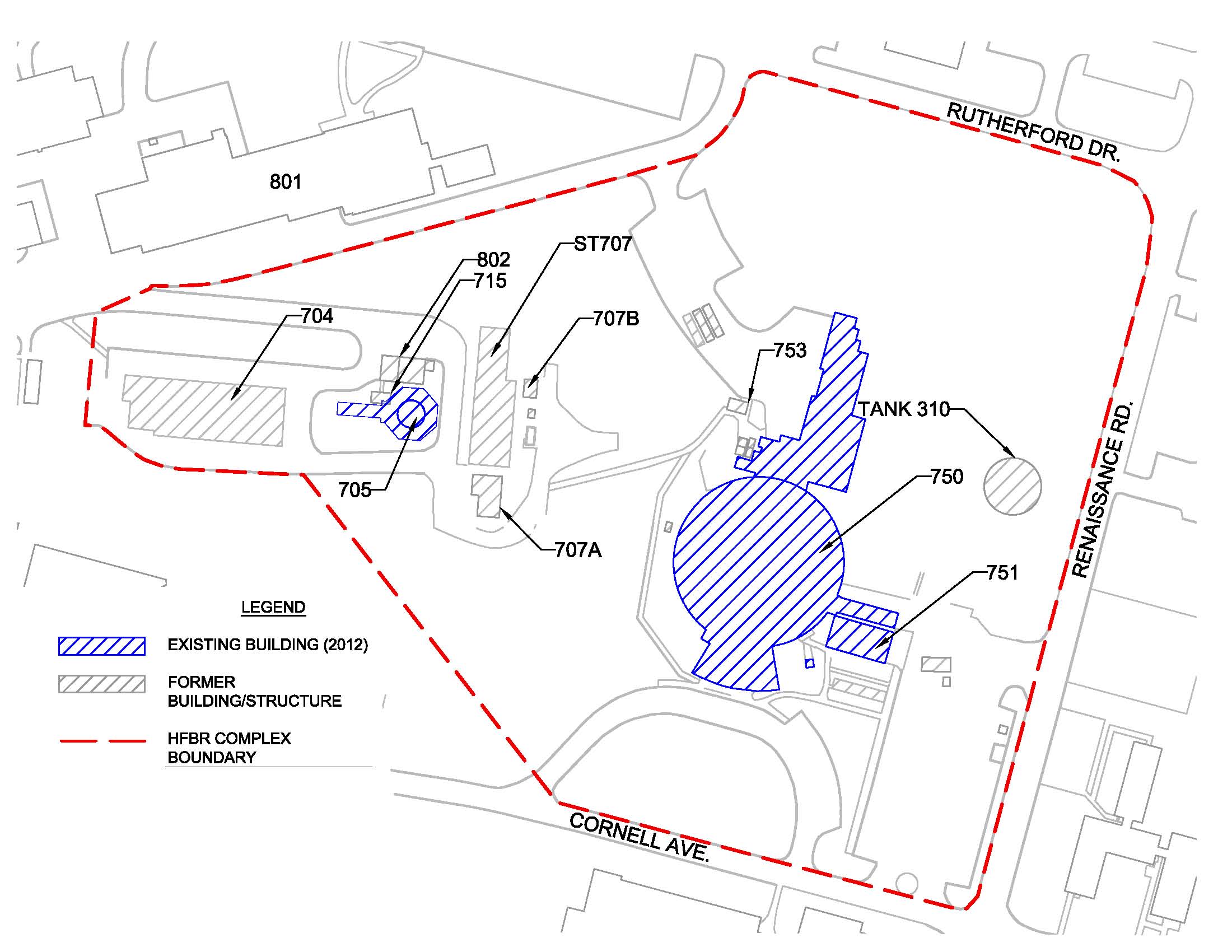
Figure 1