Ion Irradiation / Implantation
The Brookhaven Tandem Van de Graaff Facility has a long history of providing irradiation and ion implantation services for users. A new High Energy Implanter has been built to provide ions for deep implantation into Silicon Carbide wafers. Conventional implanters are limited to implantation depth of less than 1mm. By taking advantages of the unique capabilities of the BNL Tandem Van de Graaff, the High Energy Implanter1 can provide a uniform implantation from the surface to a depth of greater than 15 mm.
BNL High Energy Implanter
The BNL High Energy Implanter uses an existing beam line (Fig. 1) with the unique feature that the diameter of the beam pipe gradually increases from 100 mm to 710 mm just before the end vacuum chamber. This feature allows the beam to be swept over a wide area.
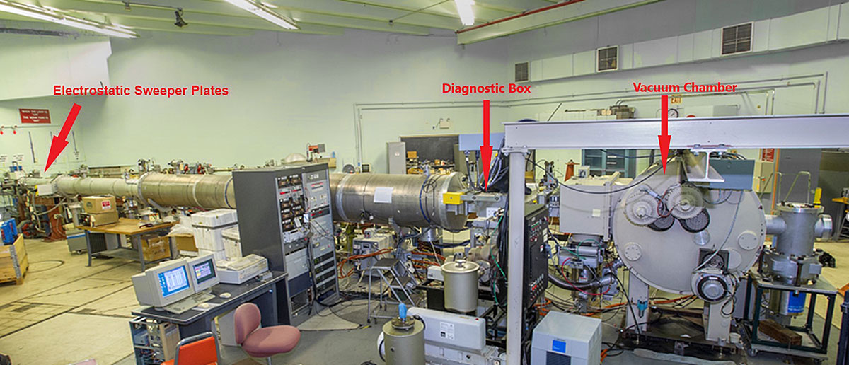
Fig. 1: High Energy Implanter beam line
The High Energy Implanter (Fig. 2) consists of a pair of horizontal deflector plates, faraday cups, stationary aluminum foil energy absorber and a vertically moving SiC wafer support plate attached to a linear stage. The horizontal deflector plates will sweep the beam horizontally while the linear stage moves the SiC wafers through the swept ion beam. The faraday cups monitor the beam intensity during the implantation and the aluminum foil energy absorber degrades the beam energy to allow implantation of the ions to the surface of the SiC wafers.
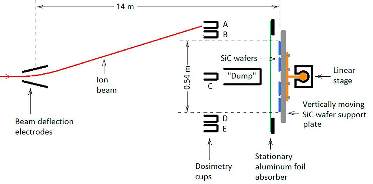
Fig. 2: Schematic of the High Energy Implanter
The wafers are mounted on a support plate which is connected to a linear stage (Fig. 3) that drives the wafers vertically through the ion beam. The support plate can hold a maximum of eight 4-inch wafers (Fig. 4). The maximum travel of the linear stage is 300 mm at a speed of approximately 10 mm/sec. The relatively slow speed of the linear stage coupled with the 400 Hz of the ion beam sweep make sure that the implantation is very uniform. To further ensure uniform implantation, the wafers make several passes through the beam at each energy. During operation the center cup provides feedback to the control system to adjust the speed of the linear stage.
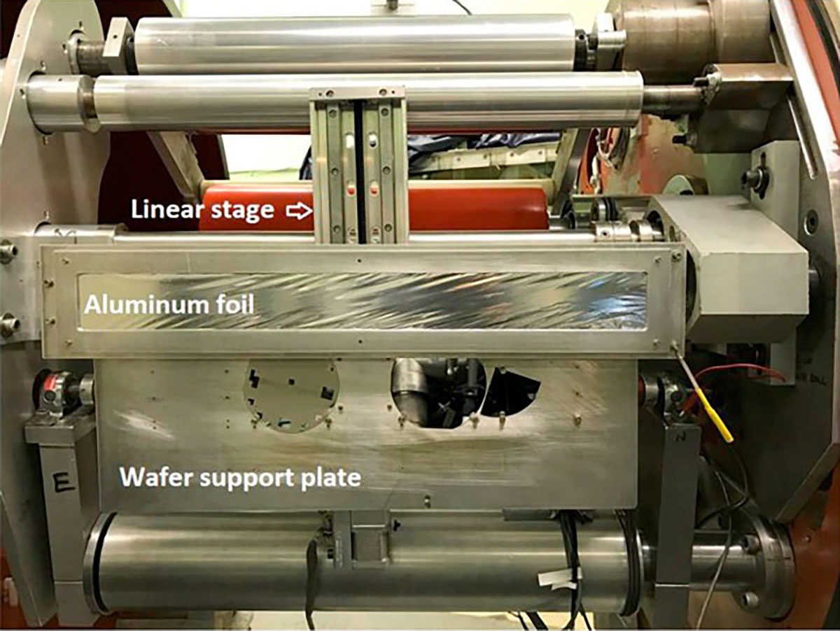
Fig. 3: Photograph of Wafer support plate and linear stage
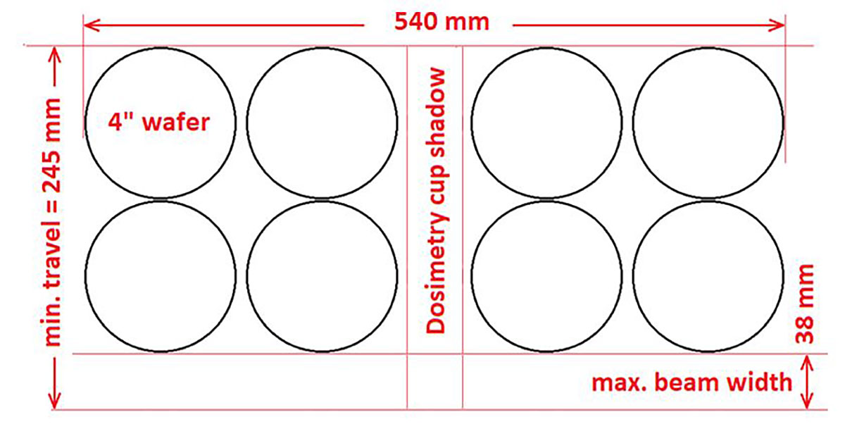
Fig. 4: Layout of eight 4” wafers on the support plate.
Implantation Results
By doing a series of implantations at discreet ion beam energies, a uniform ion implantation can be built from the maximum depth to the surface, as shown in Figure 5.
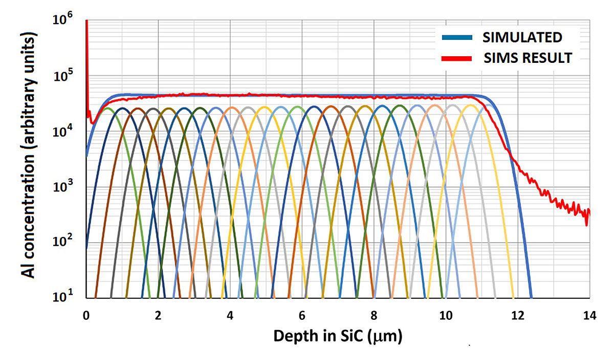
Fig. 5: The simulation and the SIMS analysis an aluminum implantation.
The dosimetry of the system is accurate to 2%. The implantation concentration is controllable by the length of the implantation time and the ion beam flux.
Future Plans
To date, the High Energy Implanter has been used for implantation of Aluminum and Nitrogen ions in Silicon Carbide. There are plans to increase the ions available for implantation including those of interest in Gallium Nitride.
There are also plans to add the capability of heating the wafers (Fig. 6) during the implantation process. This system is currently being commissioned and should be available for Users soon.
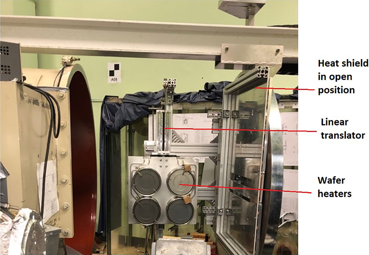
Fig. 6: System for heating the wafers during implantation
Contact Us
For more information or to book time on the High Energy Implanter contact us
Reference
[1] Nuclear Inst. And Methods in Physics Research B 442 (2019) 36-40