Linear Collider Final Focus Magnet Construction
Cable Wound Two Layer Quadrupole Shielding Coil
Near the interaction region if the ILC, the exit beam by design, is very close to the final focus quads, and is sensitive to the external field of the quads.
To eliminate this effect and prevent disruption of the exiting beams, a two layer shielding quadrupole has been designed and wound. For simplicity as well as efficiency, the transfer function of this coilset has been designed to allow series connection of the focus quad with this outer shield coilset.
The completed magnet will be finished with G-10 fillers, voltage taps and heaters will be added, blue epoxy filling for all interstitial spaces, and then the magnet will be wrapped with glass cloth and fiberglass roving, then cured. Once cured, this magnet will be capable of full power operation either standalone, or mounted outside the six layer quad magnet.
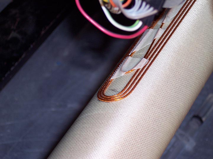
Figure 26 shows the lead end of the coilset three turns into the winding of the first layer. Note that in the winding process, the start lead is folded back out of the way, and will be routed next to the end lead to cancel the lead field.
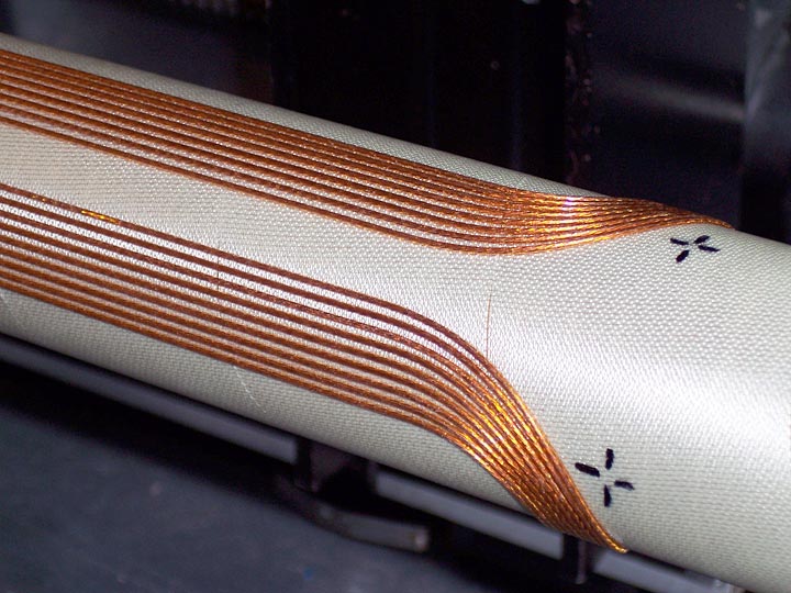
Figure 27 shows the non lead end of the first layer during the winding of the ninth turn of the first layer. The wider spacing of the straight section is clearly evident here, as is the tighter packing of the wires in the end turns; this variable spacing being a design feature embedded into the direct wind capability.
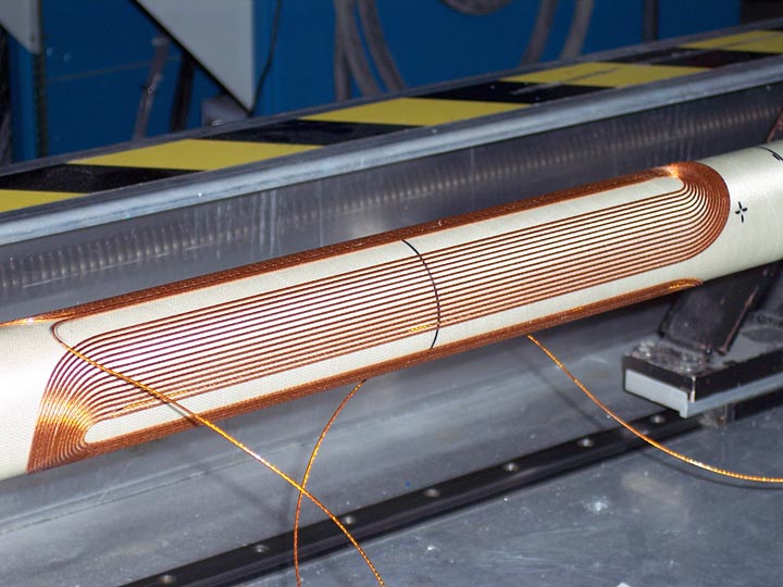
Figure 28 shows the completed first layer of the coil pair. Visible is the wire which will make the transition to the second layer coil. Using this process, no solder joints between layers are required. The next step is the addition of the G-10 filler pieces and the matched expansion blue epoxy between the wires.
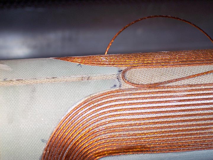
Figure 29 shows the g-10 saddles at the lead end of the magnet prior to blue epoxy fill.
Figure 30 shows the start of the second layer.
Figure 31 is the completed second layer. Note the two leads arrive at the same location. This allows the leads to be bundled together to reduce error fields. Also visible is the transition wire from layer 1 to layer 2.
Figure 32 shows a closeup of the second layer at the non lead end. Note here the tighter spacing of the wires, both in the straight section and in the end.