J-PARC Correctors
Combined Function Magnet
Both of the coil designs are two layer serpentine designs using “six around one” cable. The skew dipole is the first coil to be wound as it is the simplest from a coding and e/m analysis point of view.
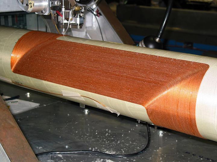
Figure 1 shows the first layer of the skew dipole nearing completion. Of note is the lack of harmonic correction spacers within the body of the coil. This is made possible by the the two step wiring process, which allows the two layers of the coil to be entirely independent of each other. Previously, the nested wire type of design locked the second layer of the coil into the same pattern already established on the first. By isolating each, it is now possible to eliminate the harmonic error correction function from the first layer, and incorporate it entirely within the second, thereby speeding up the assembly process by the elimination of additional g-10 piece parts.
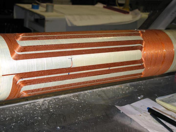
The second layer of the skew dipole, figure 2, shows a far more complex pattern. It is here that the harmonics for the 2-d cross section, as well as integral field, are reduced to zero. Note that the first layer start lead comes out from under the second layer, and has been placed directly alongside the exit lead of the second layer. This detail is required, as the contribution of the leads to the field cannot be ignored for magnets of this short length and large radius. Both coils are 600 mm in length, and 81 mm in radius. This coil will remain as seen, until the completion of the combined function coil, at which point all the second layer g-10 pieces will be applied and the entire package over-wrapped with s-glass and cured.
The initial design of the combined function corrector required careful attention to detail. Since it is a combined function corrector, to be used in a combined function main magnet, the first issue to be addressed is the coupling of the corrector to the main field. Quenches occurring within the main cable magnet can dump significant energy into the corrector, destroying it. To prevent that, the corrector must be orthogonal to the field of the main magnet at the radius of the corrector coils. Initial coding efforts starting with a quadrupole serpentine are easily capable of adding low levels of dipole field. However, the levels of quad and dipole for this magnet require dipole fields close to 50 percent of the quad level. This called for a drastic solution, creating the combined function magnet as a quad first layer, with a dipole second layer.
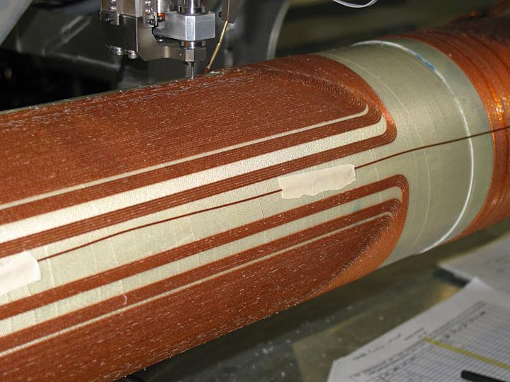
Figure 3 shows the first, quadrupole layer, of the combined function magnet after winding. Since the quad layer harmonics cannot be addressed easily within the dipole layer, it has been designed for zero harmonics on its’ own. This is evident by the introduction of several pattern spacers. The quad layer start lead is taped within the pole, and will be re-routed prior to second layer winding. Note the completed skew dipole coil on the right of the figure.
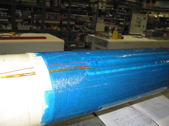
Figure 4 shows the first layer of the combined function coil after spacers and matched expansion epoxy has been added, but before the second, dipole layer.The two thicker wire leads are the stabilized skew dipole leads. They have been routed through the open section of a quad pole, along with the start lead for the combined function coil. This assembly and wire routing sequence allow both coils to be made and connected without using any more radial space than that required for the two layer coils.
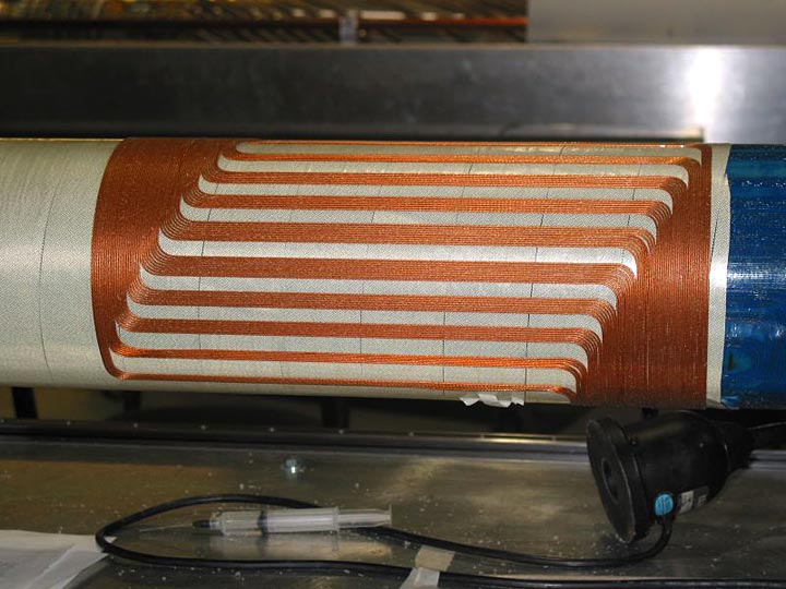
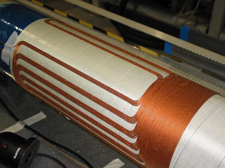
Figure 5 and 6 show the completed second layer of the combined function coil. To cancel the solenoid component of the first layer quad serpentine pattern, the second layer dipole coil requires the same number of turns. To maintain the correct quad to dipole ratio, the dipole coil length has been adjusted, and is shorter than the underlying quad. Of note is the large number of pattern spacers on the dipole portion. This is required to provide the correct two dimensional cross section required for low harmonics in the dipole layer.
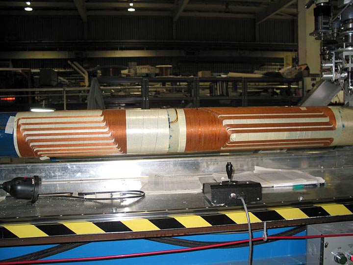
Figure 7 shows the final magnet, with all coils completed. On the far right side, the exit leads for both coils are visible; the larger pair is the stabilized skew dipole, and the two smaller are the newly completed combined function leads.
This support tube is now complete with respect to computer winding, and will now be removed from the machine for fitting of the g-10 piece parts on both coils, lead stabilization, final overwrap and cure, and then warm measurements.