J-PARC Correctors
Interconnect Corrector Magnet
The design of these steering correction magnets has them being placed in the interconnect regions between the cable magnets. Since they are located in a vacuum, they will not be in direct contact with the helium cooling flow, but instead, require cooling be done through conduction.
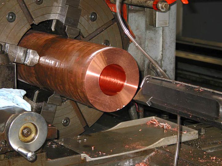
Figure 8. To aid in heat transfer, the corrector tube is machined entirely out of copper.
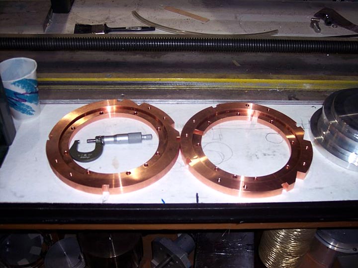
Figure 9. To maximize the operating thermal margin, the coil pattern comes within 10 mm of the end flanges. This required making the end flanges as separate parts, to be attached after winding.
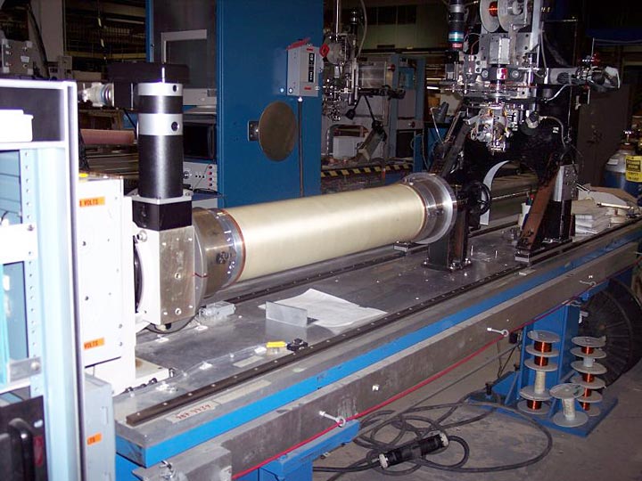
Figure 10. After the support tube is insulated with Kapton insulation, it is covered with the b stage fiberglass winding substrate, mounted to the wiring machine.
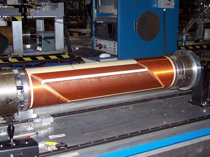
Figure 11 shows the completed first layer of the normal dipole.
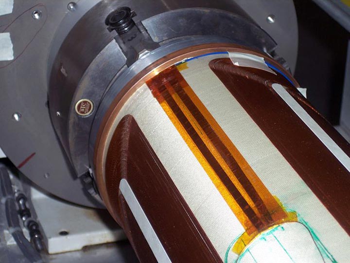
Figure 12 details the center tap connections for the quench detection circuitry. Of note is the use of 3 mil thick copper tape for these connections, as the standard tefzel over kapton wrap 30 gauge wire is thicker than the conductor and would disturb subsequent layer concentricity. The 30 gauge wire can be seen at the lead end of the magnet, color blue.
This finished first layer is nomex filled, in locations where wire is not present, and all voids are filled with 2851 stycast two part epoxy and allowed to cure. The nomex layer and blue epoxy layer return the surface to a cylindrical one, allowing the second wiring layer to be placed, without regard to the topology of the first wire layer. This flexibility allows the first layer to be optimized for transfer function, whereas the second layer is used for transfer function as well as zeroing harmonics. Second layer winding is the next step.
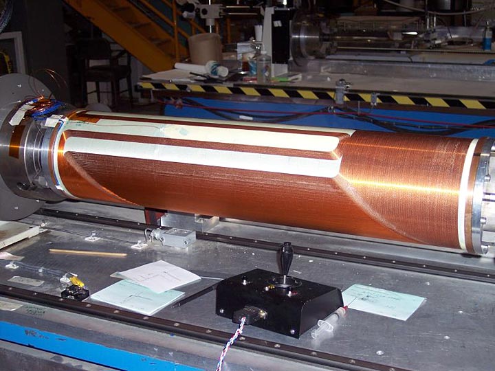
Figure 13 is the completed second layer of the dipole. After the voltage taps and spot heaters are installed, the dipole is wrapped with S glass and cured.
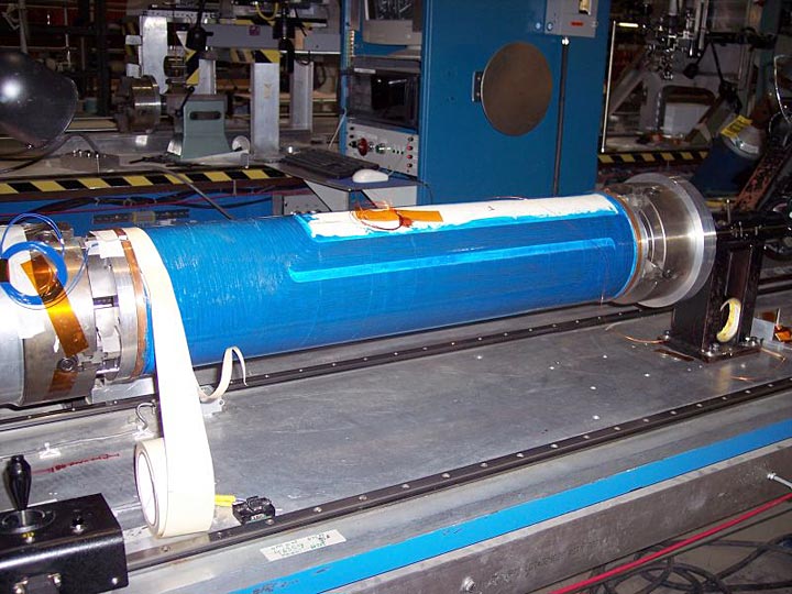
Figure 14 shows the first layer of the skew dipole complete, with the nomex filler pieces and blue epoxy covering the coil.
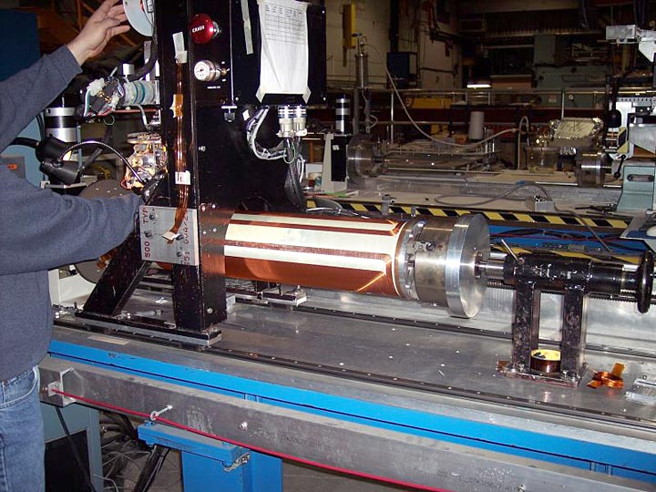
Figure 15 shows the skew dipole layer two in process.
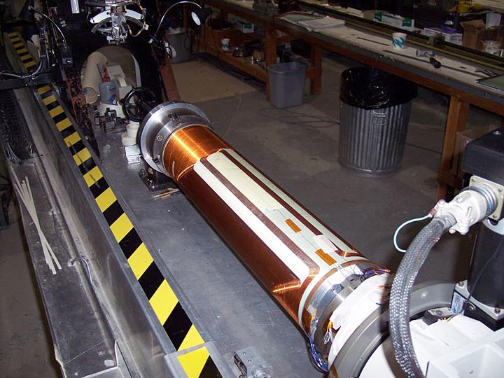
Figure 16 shows the skew dipole complete.