Linear Collider Final Focus Magnet Construction
Cable Wound Six Layer Quadrupole
The incoming beam final quad for the linear collider 20 mr option requires a gradient of 140 T/m within a solenoid of 3 Tesla. To meet this goal, a design using 6 around 1 cable bonded to a one inch diameter tube was used. The magnet design required 6 layers of this cable. Two layers were bonded at a time, with S-glass compression wrap every two layers.
Final cold testing results were very good, with only two training quenches before reaching short sample. Initial test results at a glance:
| Background Field Tesla | Temp Kelvin | Gradient T/m |
|---|---|---|
| 3 | 4.3 | 158 |
| 4 | 4.22 | 139 |
| 5 | 4.22 | 134 |
| 6 | 3 | 137 |
This data scales to 232 Tesla/meter at 1.9 Kelvin in a 3 Tesla background field. Present field requirements for the 20 mr IR represents 60% of the magnet capability, a comfortable margin. Indeed, even at 4.3 Kelvin in a 3 Tesla field, the magnet performed 13% above the operating gradient.
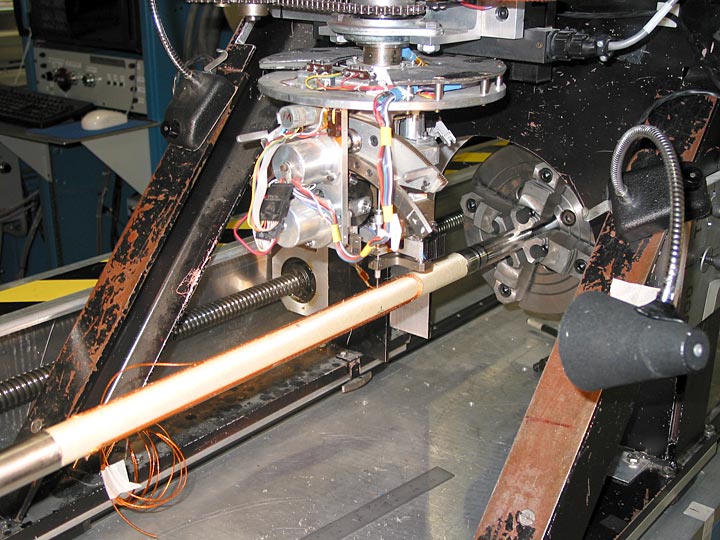
Figure 16 shows the first layer of cable being planted.
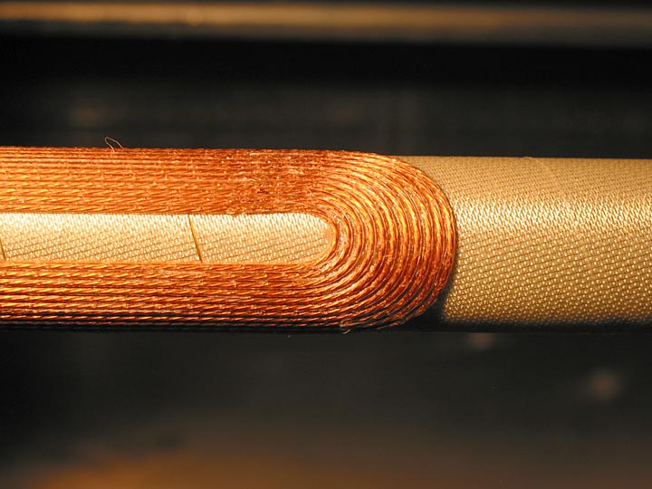
Figure 17 is a close up of the non lead end of the first layer.
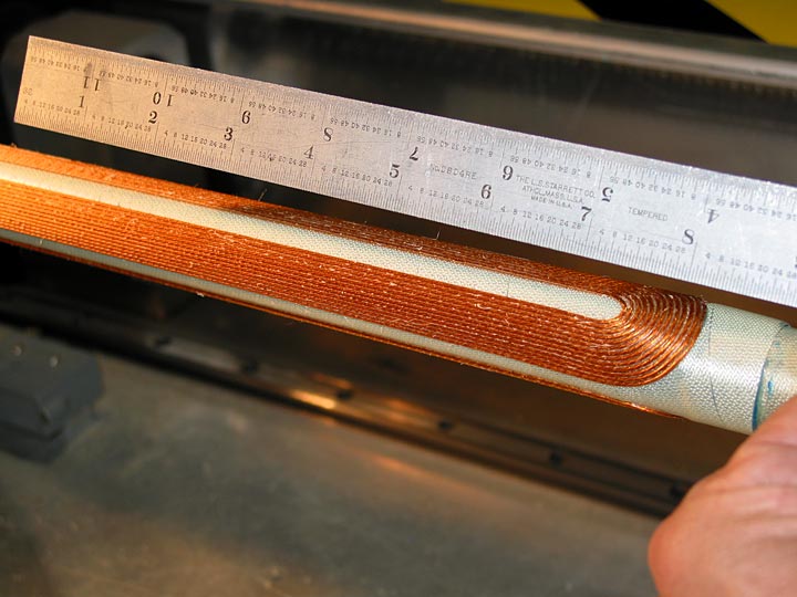
Figure 18 is a view of the completed second layer.
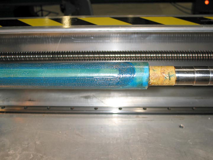
At the end of each layer, the poles and end saddles are filled with G-10 pieces. These are bonded to the bottom substrate first, and then all interstitial spaces are filled with matched expansion epoxy. This epoxy is seen in Figure 19, this view being the completion of the fourth layer of cable.
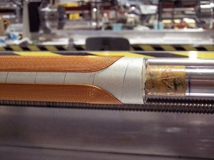
Figure 20 shows the non lead end of the sixth layer of the magnet.
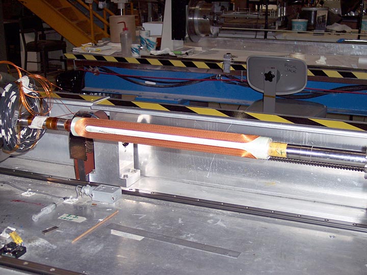
Figure 21 shows an overall view of the completed magnet. After the g-10 fillers and epoxy filler are added, the magnet is over-wrapped with S-glass roving. Once cured, this structure is capable of supporting the internal coils against Lorentz forces without any additional external structure. The final outer dimension for this coilset is 1.7 inches for 6 layers, this is 58.3 mils per layer of conductor (2.3 mm per layer), including the S glass roving required for pre-compression.
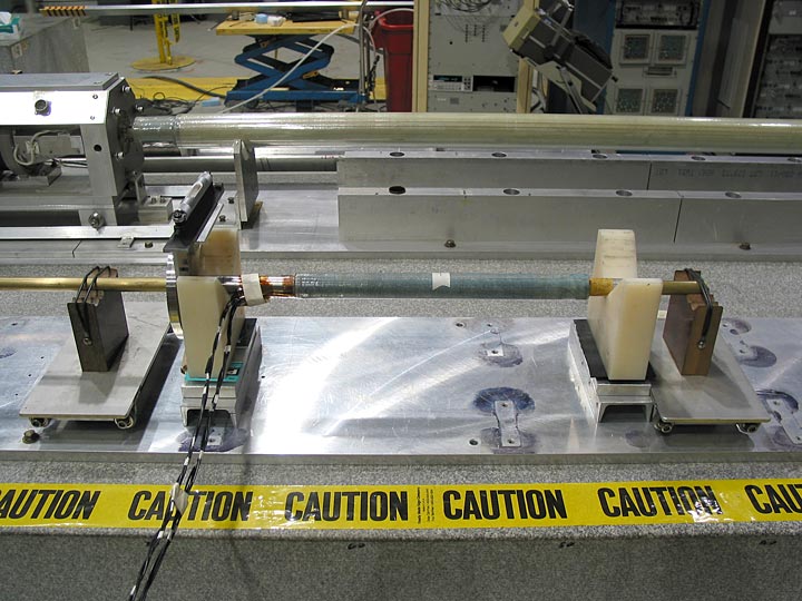
Figure 22 is the test magnet in warm magnetic measurement after winding of the 4th layer. Once the harmonics of the first 4 layers are measured, the last two layers are modulated to cancel the measured harmonics. After all six layers were wound, the worst harmonic present at the reference radius of 5mm was the skew octupole, at 1.49 units. This highlights the strength of modulation based harmonic cancellation, a design feature of the Direct Wind process.

Figure 23 is the final magnet being prepared for cold testing.
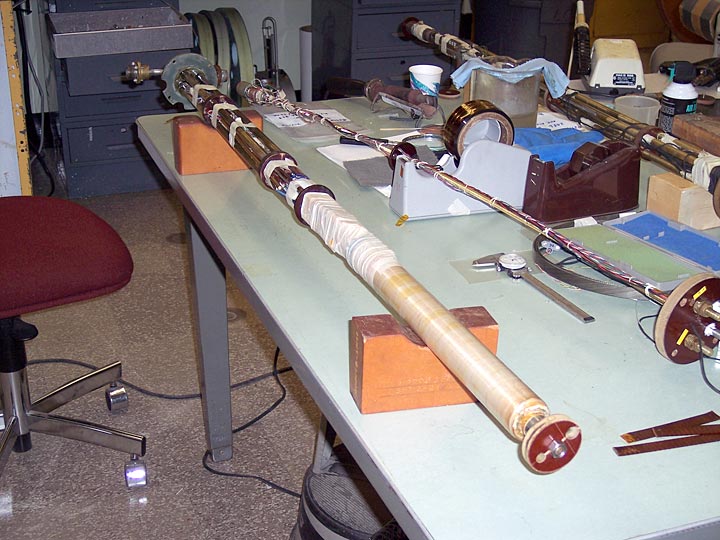
Figure 24 is the final magnet being prepared for cold testing.