NSRL User Guide: Biology Experiments
I. Beamline Hardware
Incubators
NSRL has two incubators available for use that have been modified to allow samples requiring strict environmental controls to be placed in the beam for long exposures. The smaller one is for use with a standard 15 x 15 cm2 beam spot, and the other is for large beam (60 x 60 cm2) applications. The incubators provide a temperature and humidity controlled enclosure, with thin kapton windows that allow passage of the beam with minimal interaction. CO2 can be delivered to both of the incubators to allow environments with controlled carbon dioxide atmospheres, typically at about 5%.
The small incubator itself can be mounted on the rails in the target room so that users can prepare their samples in the cell preparation rooms, and then roll the incubator into the target room for easy placement in the beam. The dimensions of the inside of the incubator are [need numbers here]. Several photographs below show the incubator mounted on the beamline rails in the NSRL Target Room ready to take beam.
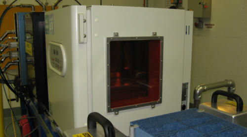
Figure 1 shows the Small Incubator mounted on the rails between the sample flipper and the Digital Beam Imager.
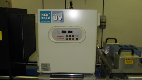
Figure 2 shows the Small Incubator from the side.
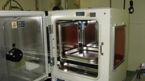
Figure 3 shows the Small Incubator with the two doors open. Inside is the tray for secondary containment of samples.
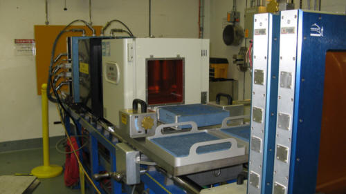
Figure 4 shows a long view of the Small Incubator including 2 of the 3 upstream ion chambers.
Note that in most cases it is important to keep the entire beam inside the kapton window of the incubator to prevent beam scattering and fragmentation in the heavy metal walls of the incubator. Such interaction would modify the dose being observed inside the incubator. The size of the usable beam spot giving uniform exposure inside the incubator is approximately 15 x 15 cm2, as can be seen in the images below.
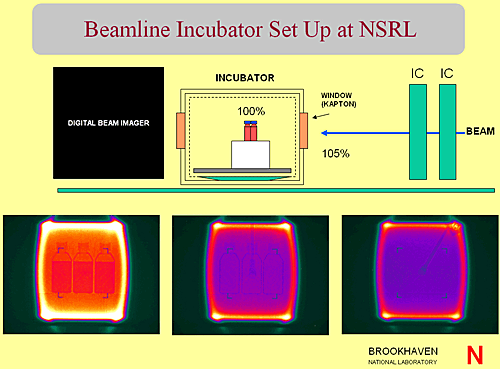
Figure 5 shows a schematic of the incubator aligned in the beam between the two ion chambers on the right and the Digital Beam Imager on the left. The first of the three images show 3 T75 flasks inside the incubator. The second image shows the three flasks again with the calibration device (EGG counter) in front of the incubator extended from the top of the image into the center. The third image shows the flasks removed and the EGG inserted into the incubator at the location of the samples.
For large beam applications, experimenters can make use of the large incubator. It also has heaters, and hot water trays as well as CO2 injection and monitoring.
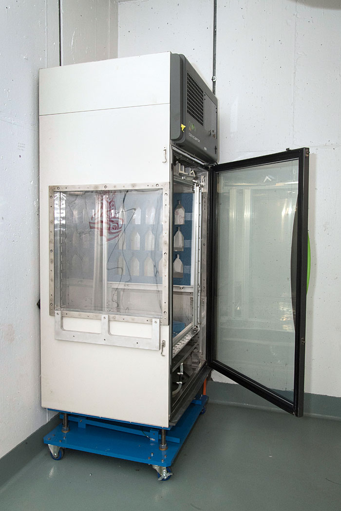
Figure 6 shows a photograph of the large incubator with blue foam sample holders in place.