NSRL User Guide: Biology Experiments
II. Operations
Stacking Samples
General Considerations
When planning beam time requests, an important consideration is how many samples can be exposed at the same time. The large beam spot with uniform illumination (about 20 x 20 cm2) allows for as many as four T75 flasks or six T25 flasks to be contained within the beam center. Under certain conditions it is possible to stack multiple samples along the beam direction. The effect of stacked samples can either increase the dose or decrease the dose depending on the heavy ion being used, the beam energy, and other considerations. The details of dose delivery need careful consideration before sample stacking is utilized.
In general, for heavy ions like Fe-56, fragmentation of the primary ion in the upstream samples results in a lower dose being delivered to the downstream samples. Of course the same consideration applies to thick samples that are not stacked. There are two effects at work in the case of heavy ions. As the ion passes through the sample, it slows down which increases LET (in general). Heavy ions can fragment in the sample, with the resulting lower-Z fragments depositing lower LET (in general) than the primary high-Z ion. Under certain conditions it is possible for slow fragments to deposit greater LET than the primary ion would have. In cases where thick samples or multiple stacks of samples are demanded, detailed calculations are required to fully characterize the dose delivered.
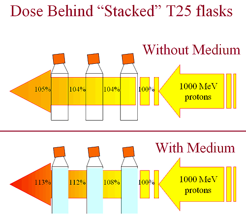
Figure 1: Measured effects of stacking 3 T25 flasks in a 1000 MeV proton beam. Top shows flasks without any medium, while the bottom shows the effect of filled flasks.
The Paradoxical Effect of Shielding
For low-Z ions and protons in particular, stacking samples can have the effect of increasing the dose delivered to downstream samples due to target fragmentation and secondary particles in the beam produced by interactions of the beam particles with the sample. As an example, 1000 MeV protons incident on an aluminum target of thickness 20 g/cm2 produced a dose profile shown in Figure 2 where the measurement is compared with the results of a simulation (PhiTs program). The dose delivered is more than 50% greater at the exit of the target than in the absence of the target. An interesting observation is that back-scattered particles elevate the dose at the upstream side of the target as well, making the dose 10% higher immediately in front of the shield.
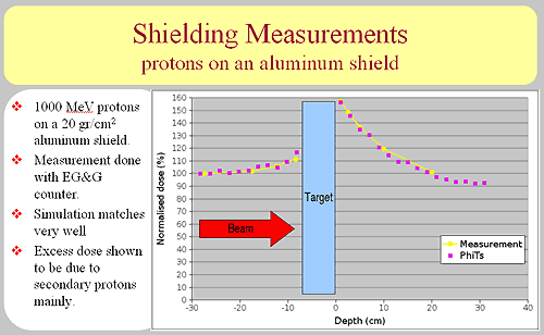
Figure 2. Comparison of measurement and simulation of the dose delivered by a 1000 MeV proton beam in the neighborhood of an aluminum shield of thickness 20 g/cm2. A detailed analysis of the simulation showed that the dose increase is due primarily to secondary protons knocked out of the aluminum shield.
At higher energies the effect increases, as illustrated with the measurement of 2500 MeV protons below. The dose rate immediately behind a shield of 15 g/cm2 aluminum is 61% higher than the nominal rate. For a shield of 50 g/cm2 thickness, the rate increase is 130%.
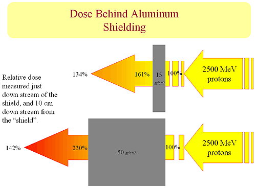
Figure 3 shows the increase in dose delivered by a 2500 MeV proton beam immediately behind an aluminum shield, and 10 cm downstream of the shield.
Advantages of Foam Sample Holders
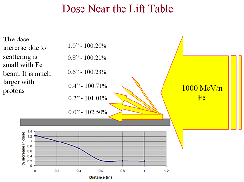
The effect of secondary particles and scattered particles applies also to samples placed on top of or close to a table or other massive surface. Measurements of dose near the surface of an aluminum table top that is in the beam show the effect. Although the magnitude of the effect is small, it should be kept in mind when deciding on sample holders and placement.